108
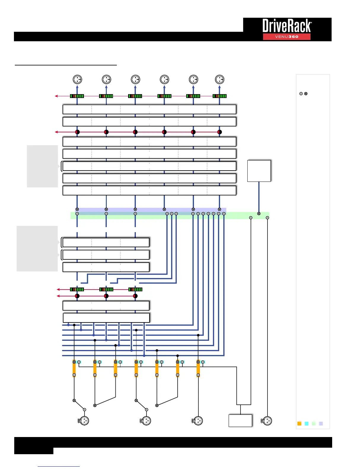
DSP Block Diagram
IN1
IN2
IN3
IN4
IN5
IN6
IN7
IN7
IN6
IN5
IN4
IN3
IN2
IN1
RTA MIC INPUT
**SIGNAL GENERATOR
SIGNAL GENERATOR
***RTA SOURCE
BUS A MID 1
MID 2
MID 3
MID 4
MID 5
MID 6
BUS 1
BUS 2
BUS 3
BUS B
BUS C
1
2
3
A
B
C
CH1
CH2
CH3
CH4
CH5
CH6
RTA
OUTPUTS
Front-Panel
OUTPUT
Meters
Front-Panel
OUTPUT
Mutes
Front-Panel
MIX/ROUTE
Mutes & Meters
Congurable Inserts:
AGC
Compressor
Noise Gate
Subharmonic Synth
Fill Delay
Congurable Inserts:
AGC
Backline Delay
31-Band Graphic EQ
Compressor
Noise Gate
12-Band Parametric EQ
Subharmonic Synth
*ANALOG1
*AES1
*AES2
*ANALOG3
*Input channel assignments: IN1: Analog1, IN2: Analog2, IN3: Analog3, IN4: AES1, IN5: AES2, IN6: AES3, IN7: AES4.
**Signal Generator can be routed to any single input (IN1-IN7) or all inputs simultaneously (IN1-IN7). Input channels are “unrouted” when Signal Generator is routed to a channel.
***RTA source selections includes: RTA Mic Input, Signal Generator, IN1-IN7, or Buses (including bus summing options listed below).
The following routing/mixing options are available for each output procesing chain: IN1, IN2, IN3, IN4, IN5, IN6, IN7, mix all inputs (IN1-IN7), Bus 1, Bus 2, Bus 3, Bus 1+2 sum, Bus 2+3 sum,
Bus 1+2+3 sum, mix Buses 1/2/3, Bus A, Bus B, Bus C, Bus A+B sum, Bus B+C sum, Bus A+B+C sum, mix Buses A/B/C.
Output
Input
ANALOG 1
AES CH 1 & 2
INPUTS
*ANALOG2
*AES3
*AES4
Inputs (IN1-IN7)
AutoEQs
Advanced Feedback Suppression
Input Inserts 2
Input Inserts 1
Input Routers/Mixers
Real Time
Analyzer
(RTA)
Signal
Generator
Mid Routers/Mixers
Mid Inserts
Crossovers
8-Band Parametric EQs
Limiters
Driver Alignment Delays