29
4.2 Preparation for assembly (Fig. 8)
• Measure the width of the door, and mark the centre line on the top edge of the door and on the lintel.
• Recommendation for the track’s proper assembly on the door’s longitudinal axis. Open the garage door completely and mark the sign
previously made on the top edge of the door on the ceiling as well.
• Open and close the door completely, and take note of the highest point reached by the door (TLP). The “TLP” is the point with the
smallest distance between the edge of the door and the ceiling.
• The distance between the TLP and the track/motor head should be 10-20 mm. It is recommended to maintain an angle equal to or
less than 30° between the towing arm and the track on the ceiling.
• Make sure that the track is perfectly horizontal with respect to the ceiling once assembled.
• If the installation is to be carried out under conditions different from those indicated, it may be necessary to use additional angular
and/or slotted mounting brackets. Any additional brackets must be cut, deburred, and mounted as shown in Fig. 8.
• For safety reasons, the suspension brackets must always be cut well below the holes to be used for fastening (Fig. 8d).
4.3 Assembly
ASSEMBLING THE TRACK (Fig. 3)
Join the two halves of the track using the coupling (verify the proper insertion side), and push until the stopper in the track is reached.
ADJUSTING THE BELT-TENSIONER (Fig. 4)
The belt’s tension must be adjusted using the tensioner on the end of the track. In order to avoid damaging the automation’s mechanical
components, the belt must not be overtightened.
MOUNTING THE TRACK ON THE CEILING (Fig. 8)
Mount the belt track in the centre with respect to your door.
Note: The centre of the garage and the centre of the door may be different.
Use tools and fastening materials that are suitable for the installation site’s conditions.
ASSEMBLING THE MOTOR HEAD ON THE CEILING TRACK (Fig. 7)
Mount the motor head on the ceiling track. Make sure that the position is correct when inserting the motor shaft into the housing. Secure
the motor head using the supplied screws. The motor head can be conveniently wired with its cable on the ground, and can then be
fastened to the track.
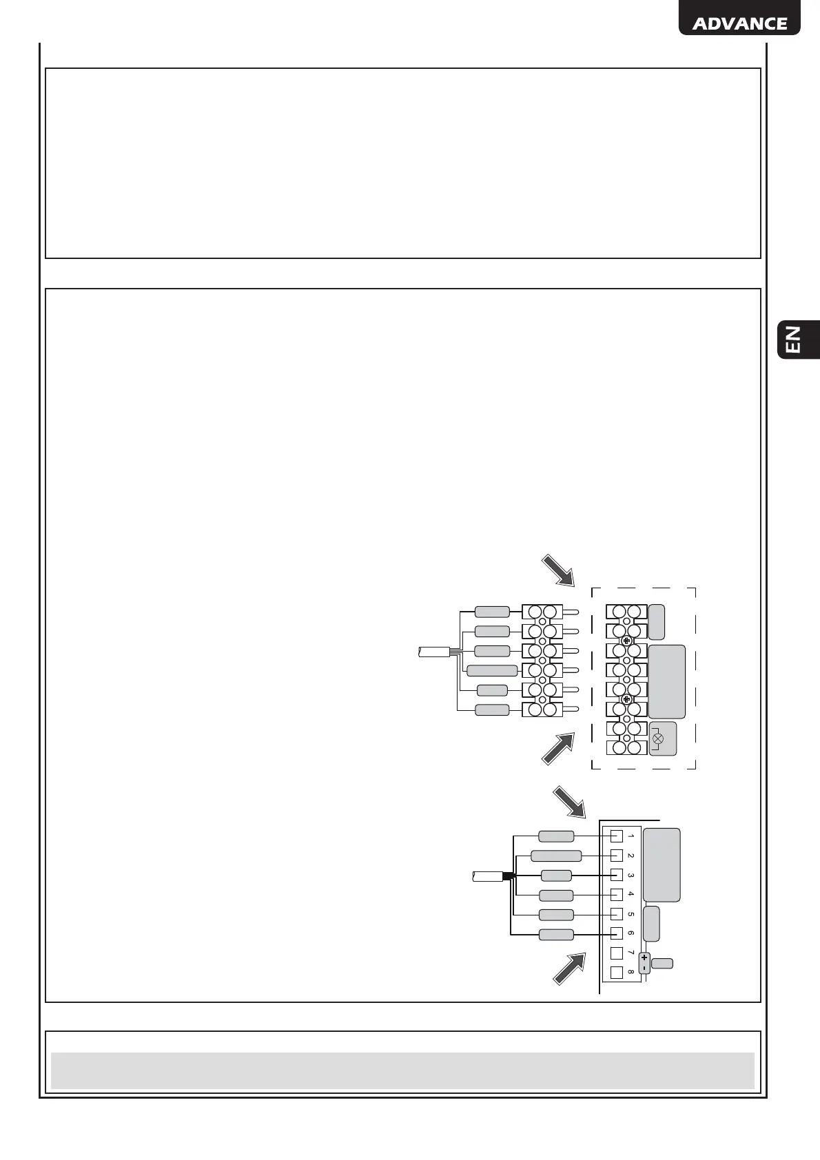
CONNECTING THE CABLE TO THE MOTOR HEAD
Connect the pre-assembled cable to the motor head shown as in
the fi gure. Secure the connection by tightening the fastening screws
on the female terminal. The “Flash” terminals are not utilized.
Plug
Motor Terminal Block
MOT 1
FLASH
ENC
ENC A
+
ENC B
-
YELLOW
GREY
BROWN
WHITE
GREEN
PINK
CONNECTING THE CABLE TO THE CONTROL UNIT (Fig. 9)
• Fasten the control unit to the wall at least 1.5 m off the ground,
using fasteners suitable for the surface.
• Insert the connection cable, into an electrical channel.
• Cut off the excess cable and connect it as shown in the adjacent
diagram, or else as shown on page. 31/33.
Control Unit
MOT 1
OUT 1
ENC (M1)
ENC A
+
ENC B
-
YELLOW
GREY
BROWN
WHITE
GREEN
PINK
4.4 How to release the gear motor (Fig. 6)
In the event of a malfunction or power failure, the motor can be released as shown in Fig. 6a or 6b in order to move the door manually.
CAUTION The safety and effi cacy of moving the automation manually is only guaranteed by DEA System if the system has been
properly installed using original accessories.