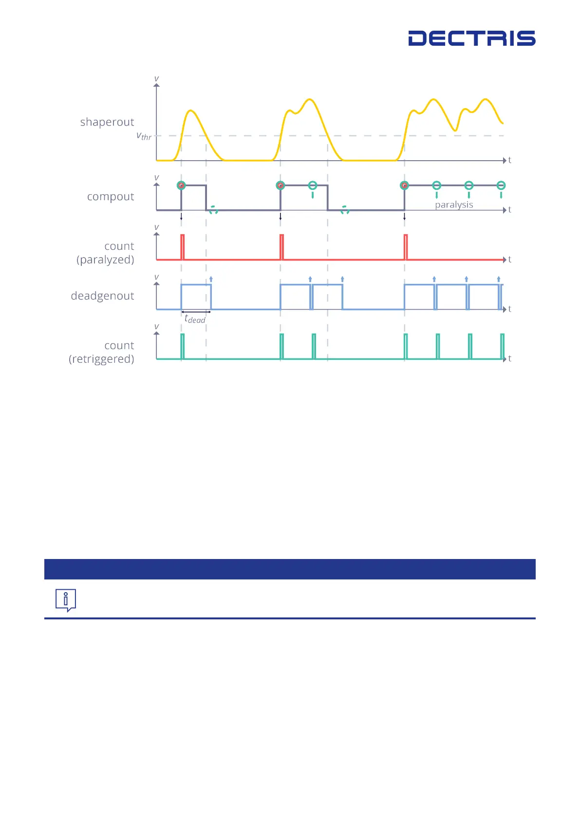
Figure 3.1: Signal Waveforms Illustrating the DECTRIS INSTANT RETRIGGER
®
technology
The Instant Retrigger principle is illustrated in gure 3.1. The rst diagram shows the signal pulses generated
by impinging photons and the eective discriminator threshold level for single photon counting. The pulse
signal includes a series of one single pulse, a pile-up of two pulses and a pile-up of multiple pulses. The sec-
ond diagram shows the corresponding digital discriminator output signal that triggers the counting circuit.
The third diagram shows the corresponding counts being registered by a conventional single photon count-
ing X-ray detector, clearly illustrating that counts are lost in the case of pulse pile-up and that this can lead
to paralyzation. The fourth diagram shows the respective dead-time generator output signal provided by a
single photon counting X-ray detector with Instant Retrigger. Here, a predened dead time interval is started
whenever a count has been registered. The fth diagram shows the corresponding counts being registered,
including potential retriggering of the counting circuit after the dead-time interval after each count. This clearly
illustrates that pulses are counted more accurately in the case of pile-up and that counting is non-paralyzable.
3.2.5. 8-bit Readout
Information #1
The 8-bit readout mode is only available with DECTRIS EIGER
®
2 X and XE detectors.
The EIGER2 ASIC allows the option to read out only the rst 8 bits of every counter instead of the full 16
bits. This enables a higher maximum frame rate at the cost of a lower dynamic range. The 8-bit mode is
automatically enabled as soon as the frame rate exceeds the maximum frame rate in 16-bit mode, as indicated
in the Technical Specications.
When using the 8-bit mode, it is important not to exceed the maximum ux per pixel, as there is no overow
protection and the counter will roll over if 255 counts are exceeded. This means the maximum ux per pixel
is 255 × frame rate in 8-bit mode.
DECTRIS EIGER
®
2 User Manual v1.8.2 6 | 36