User_Manual-PILATUS-V1_2.doc 36/57
10 Calibrating the detector
10.1 Principle
PILATUS detectors possess an adjustable threshold to suppress
fluorescence, which can be useful in many experiments. The calibration of the
PILATUS detector is necessary, because every pixel has a different
characteristic, sensitivity and count rate due to voltage drops and
nonlinearities in the analog amplifiers. To correct this irregularity, every pixel
can be adjusted with 6 trimbits (6-bit DACs) which allow 2
6
= 64 different
values. In addition the magnitude of the influence of these trimbits can be
adjusted by the voltage Vtrm.
Every detector is calibrated at our factory with at least 3 different
energy levels. This is accomplished with macros (glossary files) that perform
the steps described below.
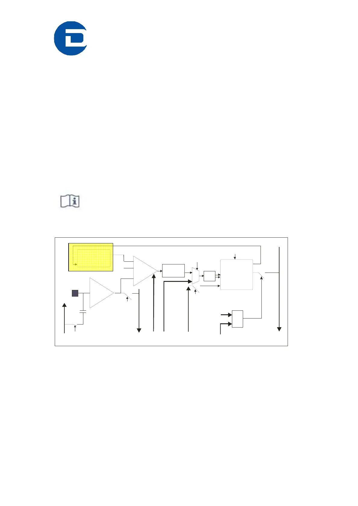
Global
Tresh
6 Bit Latch
+ DAC
CS
Amp
Comp
Bump
Pad
DOUTAOUT
Rowsel
Pixsel
Pixsel
Pixsel
Pixsel
Colsel
-
+
CAL
1.6fF
20 bit
Counter
Pixsel
Pixsel
&
PILATUS II Pixel Cell
DCLK
ENA
Pulse
Shaper
DIN
φ
1
-
Gen
φ
2
CNT/RO
Figure 15. Block diagramm of the CMOS read out chip with high lighted 6 bit latch
The detector is calibrated as follows:
Irradiate the detector with a uniform field of x-ray’s in a energy range between
4-18 keV.
Comparator (Vcmp) scan
Set all trimbits and Vtrm to zero and increase Vcmp from 0 to 0.8; recall that
0.8 corresponds to a low energy threshold, 0 to a high threshold. The result is
a Vcmp calibration curve.
Set Vcmp to the value where the detector just begins to count fully, usually the
inflection point plus the width of the S-curve.