Page 19 from 69
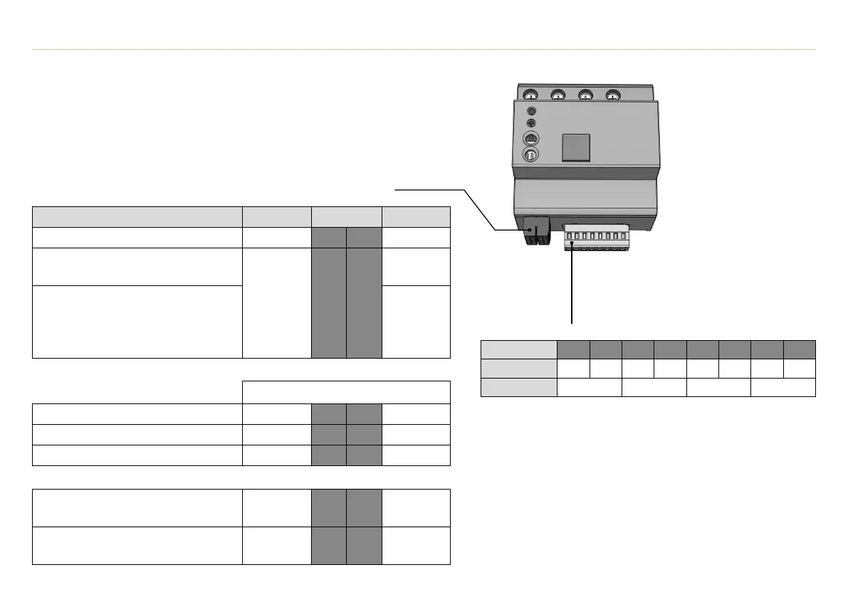
I/O connection (Input, output, supply, impulse coil)
Description Terminal
Impulse current sensor Imp2 2 1 Imp1
24 Volt version (Model DRC SD 2 ...)
Ext. power supply +24 VDC
Ue- 4 3
Ue+
(+24 V in)
230 Volt
version
(Model DRC SD 1 ...)
Auxiliary voltage, output +12 VDC,
exclusively for the operation of
the potential-free digital inputs
Ue+
(+12 V out)
⊖ Observe polarity! ⊕
Input 1: max. 30 VDC I1.2 6 5 I1.1
Input 2: max. 30 VDC I2.2 8 7 I2.1
Input 3: max. 30 VDC I3.2 10 9 I3.1
Output 1 (potential-free contact)
max. 30 V, max. 500 mA
O1.2 12 11 O1.1
Output 2 (potential-free contact)
max. 30 V, max. 500 mA
O2.2 14 13 O2.1
5. Device description (plug)
Cross-sectional area plug (push-in):
0.08 - 2.5 mm² solid-wire
0.25 -1.5 mm² with ferrule
A slotted screwdriver (size 0) is required
to unlock the push-in connectors
CM connection (Current sensors)
Terminal 1 2 3 4 5 6 7 8
Description IL1.1 IL1.2 IL2.1 IL2.2 IL3.1 IL3.2 IN.1 IN.2
Current Sensor
L1 L2 L3 N