Page 18 from 69
5. Device description
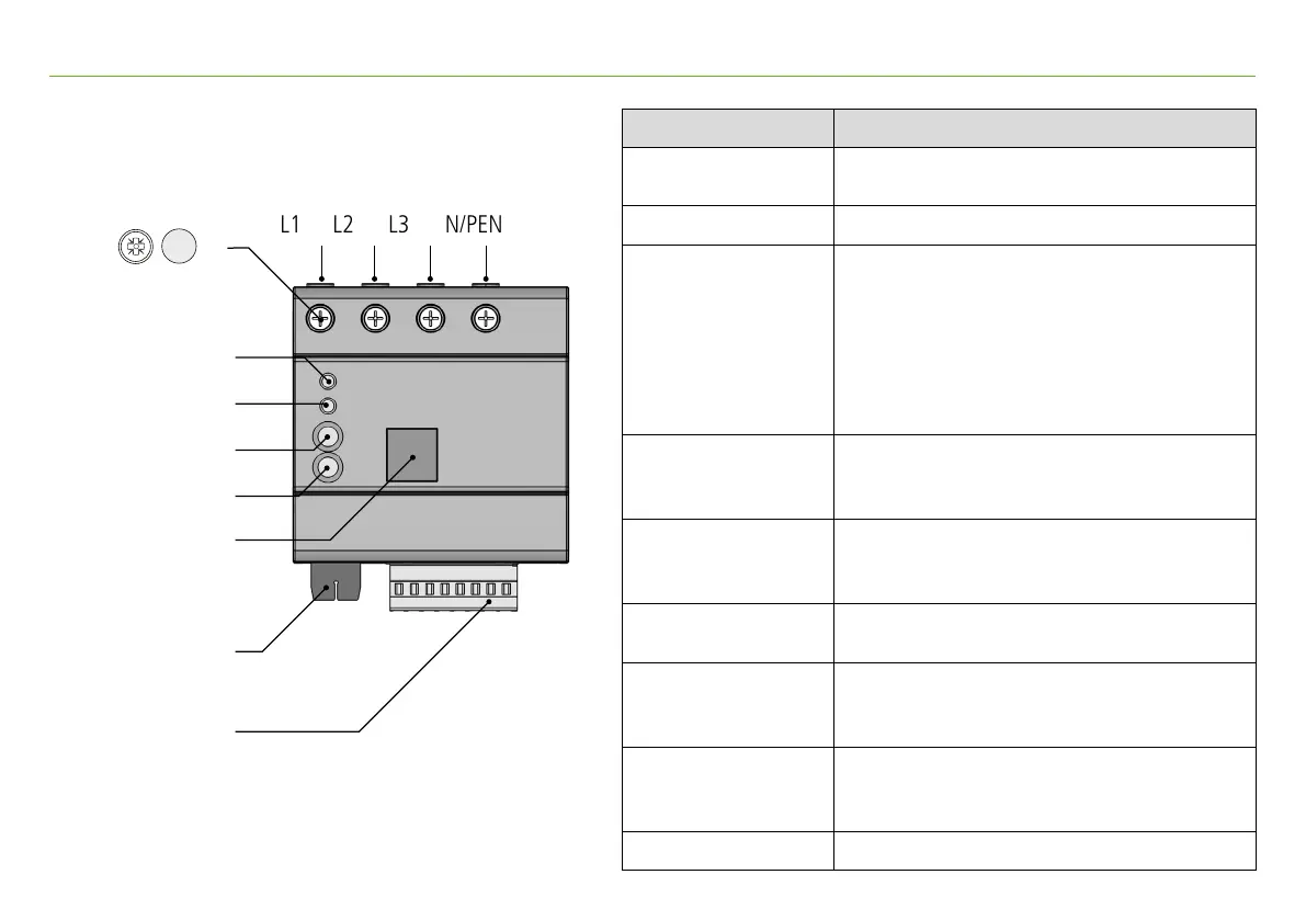
LED 1 (Device)
LED 2 (Status)
Push button 1 (Option)
Push button 2 (Basic)
Ethernet
I/O connection
CM connection
L2L1 L3 N/PEN
Description Function
L1
Measurement input and
power supply for model DRC SD 1 ...
(L1), L2, L3, N Measurement input
LED 1 (Device)
Green (flashing): Start
Green (lights up): Cloud connection active
Blue: Web server active
Yellow: Action 1 active
Red: Action 2 active
(RGB-LED, active status messages are
displayed consecutively)
LED 2 (Status)
Lights up green: power quality OK
(in factory setting, RGB-LED, can be assigned to
other device functions)
Push button 1 (Option)
Short (< 1 s): Action 1: start fast data transfer
Long (> 5 s): Action 2: device stop/start
Long (> 10 s): factory reset
Push button 2 (Basic)
Short (< 1 s): activate Web server
Long (> 5 s): device reset
Ethernet
Network connection:
Connection to internal Web server,
Modbus TCP, cloud
I/O connection
Connections for impulse current sensor,
Power supply int./ext.,
digital inputs and outputs
CM connection Connections for current sensors
Cross-sectional area: 1.5 - 6 mm² fine-stranded/stranded-wire
1.5 - 10 mm² solid-wire
A slotted screwdriver (size 0) is required to
unlock the push-in connectors
PZ 2 4 Nm