L1
L2
L3
N/PEN
5
6 4
3
11 14 12
Page 24 from 69
7. Connection
7.1 Connection DRC SD 1 1 – Part No. 910 920
Measurement inputs
L1, L2, L3 and N are connected with cables or a suitable busbar.
Power supply
The device is supplied via the measuring input L1 and N and can
bridge supply interruptions of up to 5 s. In the event of longer
interruptions, the data is recorded with reduced accuracy.
Power supply UB: 230 VAC (50 Hz), max. 30 mA
Digital inputs and outputs
The status of an SPD, for example, can also be monitored via an
input. An event can be signaled via an output channel (LED, digital
output, e-mail).
Auxiliary voltage
The auxiliary voltage (Ue+, Ue-) is used to operate the potential-
free digital inputs.
Cross-sectional area: L1/L2/L3/N: 1.5 - 6 mm
2
Cross-sectional area connector: 0.25 - 1.5 mm
2
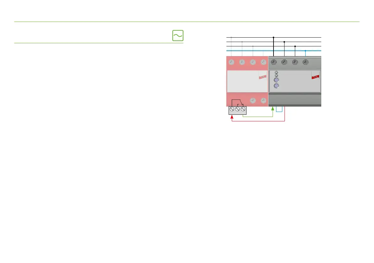
Example wiring of an SPD with remote signalling contact:
· Connect SPD-contact (terminal 11) with
auxiliary voltage 12 VDC (I/O connector terminal 3)
· Feedback from SPD contact (terminal 12 or 14)
to digital input I1.1 (I/O connector terminal 5)
· Connection ground (I/O connector terminal 4 and 6)
Configuration via the DRC web server:
The digital input is assigned to an output channel.
If the contact of the SPD opens, e.g. information is sent by e-mail,
an LED is switched or a digital output is activated.