L1
L2
L3
N/PEN
24 VDC
5
6 4
3
11 14 12
Page 25 from 69
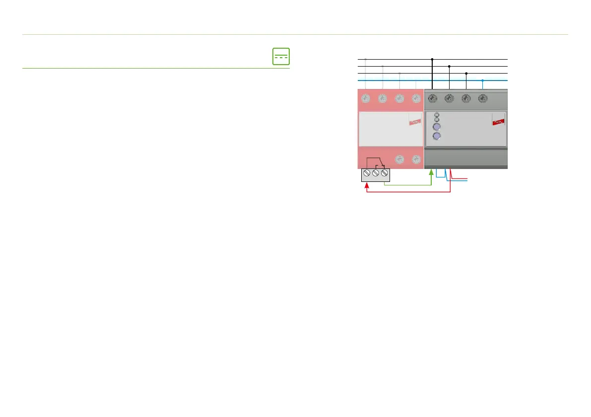
7. Connection
7.2 Connection DRC SD 2 1 – Part No. 910 921
Measurement inputs
L1, L2, L3 and N are connected with cables or a suitable busbar.
Power supply 24 VDC extern
The DRC is supplied via an uninterruptible, external voltage source.
This means that voltage interruptions and dips > 5 s can also be
recorded in accordance with EN 61000-4-30, Class A.
Digital inputs and outputs
The status of an SPD, for example, can also be monitored via an
input. An event can be signalled via an output channel (LED, digital
output, e-mail).
Cross-sectional area: L1/L2/L3/N: 1.5 - 6 mm
2
Cross-sectional area connector: 0.25 - 1.5 mm
2
Example wiring of an SPD with remote signalling contact:
· Connect SPD contact (terminal 11) with
power supply 24 VDC (I/O connector terminal 3)
· Feedback from SPD contact (terminal 12 or 14)
to digital input I1.1 (I/O connector terminal 5)
· Connection ground (I/O connector terminal 4 and 6)
Configuration via the DRC web server:
The digital input is assigned to an output channel.
If the contact of the SPD opens, e.g. an information is sent by e-
mail, an LED is switched or a digital output is activated.