Page 30 from 69
9.1 User interface
User interface – LEDs
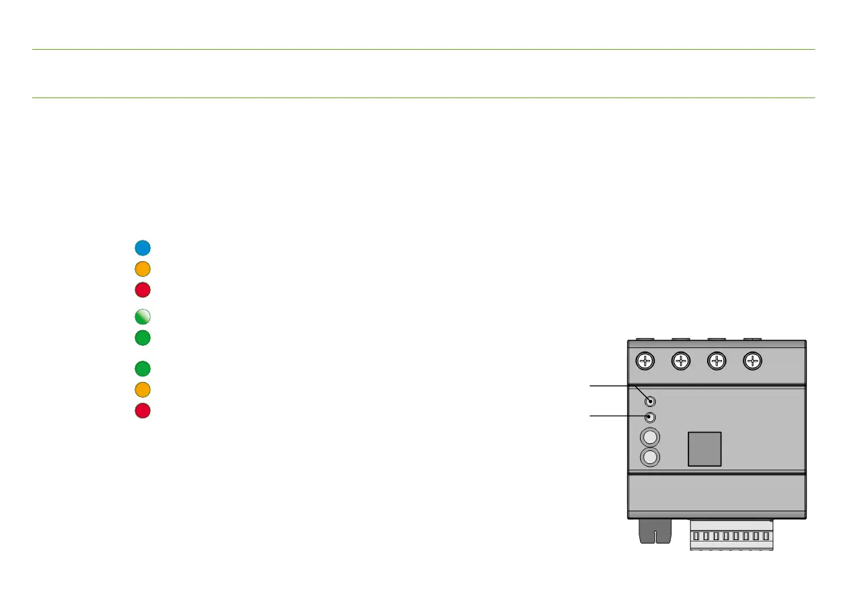
The display on the device is by means of 2 RGB LEDs.
These also differ by flashing or lighting up permanently.
Simultaneously active operating states are indicated by LED 1 (Device) one after the other.
Display with standard configuration
LED 1 (Device)
blue Web server active
orange Action 1 (Factory setting: fast data transfer)
red Action 2 (Factory setting: device stop/start)
green flashing Power supply ok
green Cloud connection ok
LED 2 (Status)
green PQ ok
orange e.g. PQ in tolerance
red PQ out of tolerance
Further signals can be configured.
The assignment of LED 2 (Status) to a measuring function
is done via the device settings.
9. Functionality
LED 1 (Device)
LED 2 (Status)