Figure 3 Cable management assembly (CMA)
Identify the rack location to install the system
Identify the designated location for the system controller or controllers in the rack.
When using systems with ES30 shelves, the designated location is U13-U14 in rack 1.
When using systems with DS60 shelves, the designated location is U22-U23 in rack 1.
The designated slots in the rack are the recommended location for the systems to
support the cabling described in this document. Other locations may require different
cable lengths for some configurations.
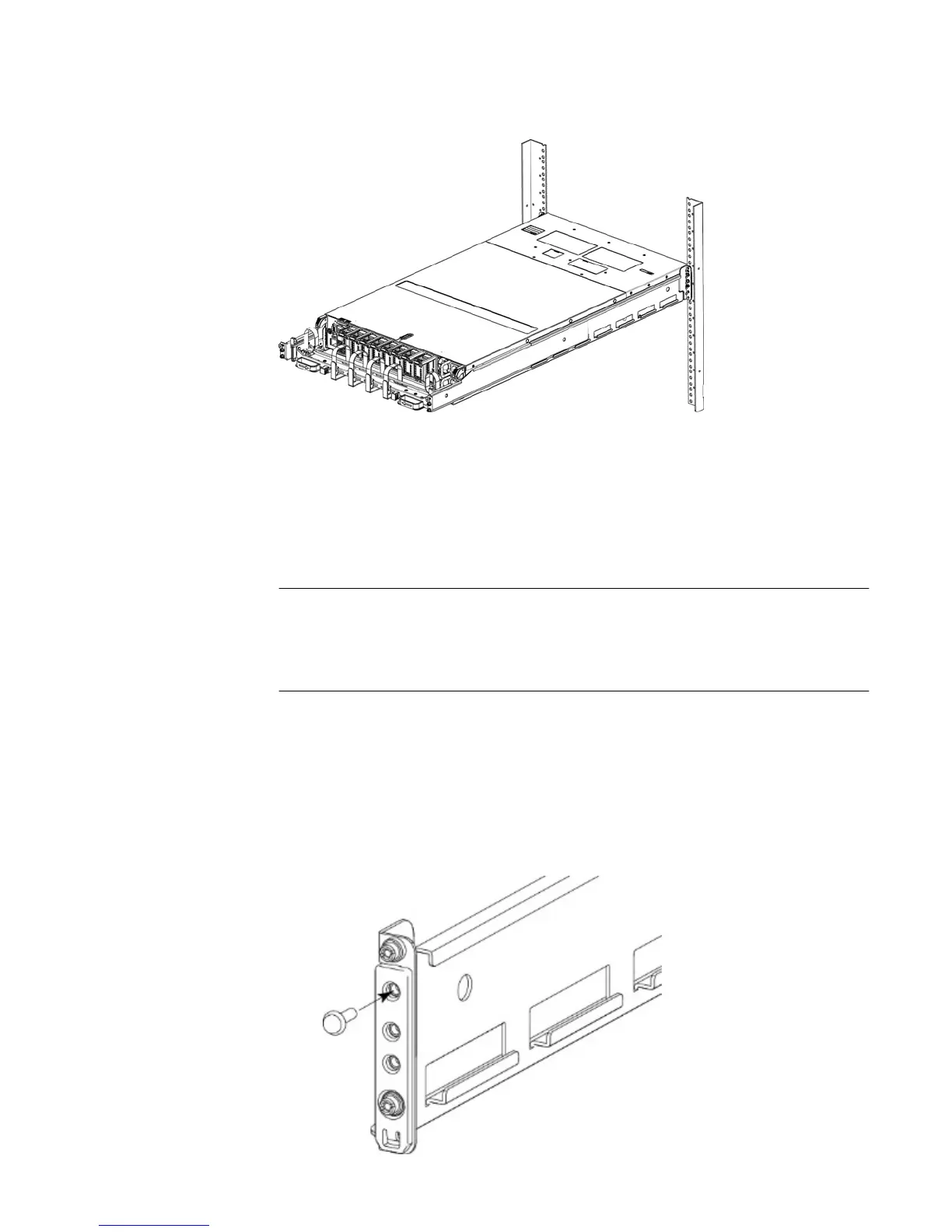
Install the rails
This procedures describes how to install the mounting rails.
Procedure
1. If EIA rail mounting holes of 7.1 MM diameter round, or M5, 12-24, 10-32
threaded, are being used, install the filler using the pin as shown. If not, proceed
to the next step.
Install the System in the Rack
Identify the rack location to install the system 15