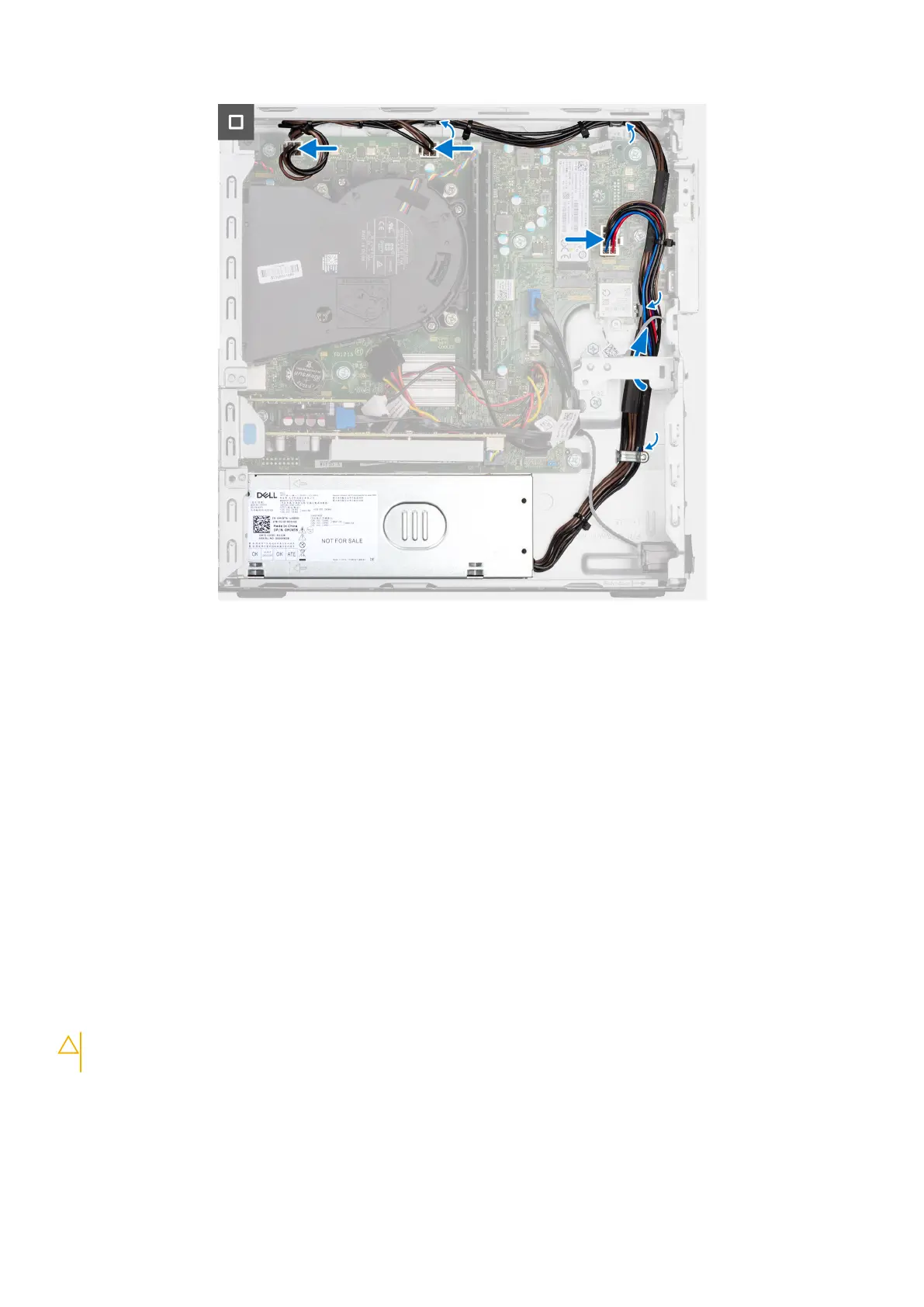
Steps
1. Place the power-supply unit on the chassis and slide it towards the back of the chassis.
2. Replace the three (M6-32) screws to secure the power-supply unit to the chassis.
3. Route the power-supply cables through their routing guides on the chassis.
4. Connect the power-supply cables to their connectors on the system board.
Next steps
1. Install the disk-drive cage.
2. Install the 3.5-inch hard drive if applicable.
3. Install the 2.5-inch hard drive if applicable.
4. Install the front bezel.
5. Install the side cover.
6. Follow the procedure in After working inside your computer.
Gruppo ventola del processore e dissipatore di calore
Rimozione del gruppo ventola del processore e dissipatore di calore
ATTENZIONE:
Le informazioni contenute in questa sezione sono destinate solo ai tecnici di assistenza
autorizzati.
Prerequisiti
1. Seguire le procedure descritte in Prima di effettuare interventi sui componenti interni del computer.
2. Rimuovere il pannello laterale.
3. Rimuovere il pannello anteriore.
76
Rimozione e installazione di unità sostituibili sul campo (FRU)