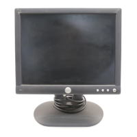
Do you have a question about the Dell E152FPc and is the answer not in the manual?
Connect power cord and video cable, then press power button to turn on the monitor.
Details on Power Button, Brightness Button, Auto Adjust Key, and Power Indicator states.
Steps to navigate the OSD menu, select functions, and adjust picture settings like Horizontal/Vertical.
Details of the 15-pin D-sub connector pins and their functions.
List of supported display modes with horizontal/vertical frequency, pixel clock, and sync polarity.
Input requirements (voltage, frequency, current) and output requirements (voltage, current, ripple).
Features and characteristics of the LCD panel, including resolution, pixel pitch, and display colors.
Diagram showing all components of the monitor disassembled, with part identification.
Visual representation of the monitor's software operational flow and decision points.
Schematic of the main board's electrical components and their interconnections.
Detailed circuit diagram for the main board, showing component connections and values.
Circuit diagram for the PWPC (Power) board, detailing its components and connections.
Top and bottom layer layout diagrams for the main board, showing component placement.
Top and bottom layer layout diagrams for the PWPC board, showing component placement.
Layout diagram for the keypad board, indicating component placement.
List of essential equipment and tools needed for monitor maintenance and repair.
Step-by-step troubleshooting for common monitor issues on main, PWPC, and keypad boards.
Procedure to adjust gain and offset automatically using the 'Auto Level' function.
Steps to adjust Red, Green, and Blue for sRGB mode to achieve target color temperature.
Steps to adjust Red, Green, and Blue for Color1 mode to achieve target color temperature.
Steps to adjust Red, Green, and Blue for Color2 mode to achieve target color temperature.
Criteria for accepting or rejecting display defects based on visual inspection of spots and lines.
Criteria for accepting or rejecting display defects based on electrical inspection of bright and dark dots.
 Loading...