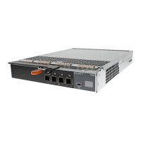
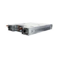
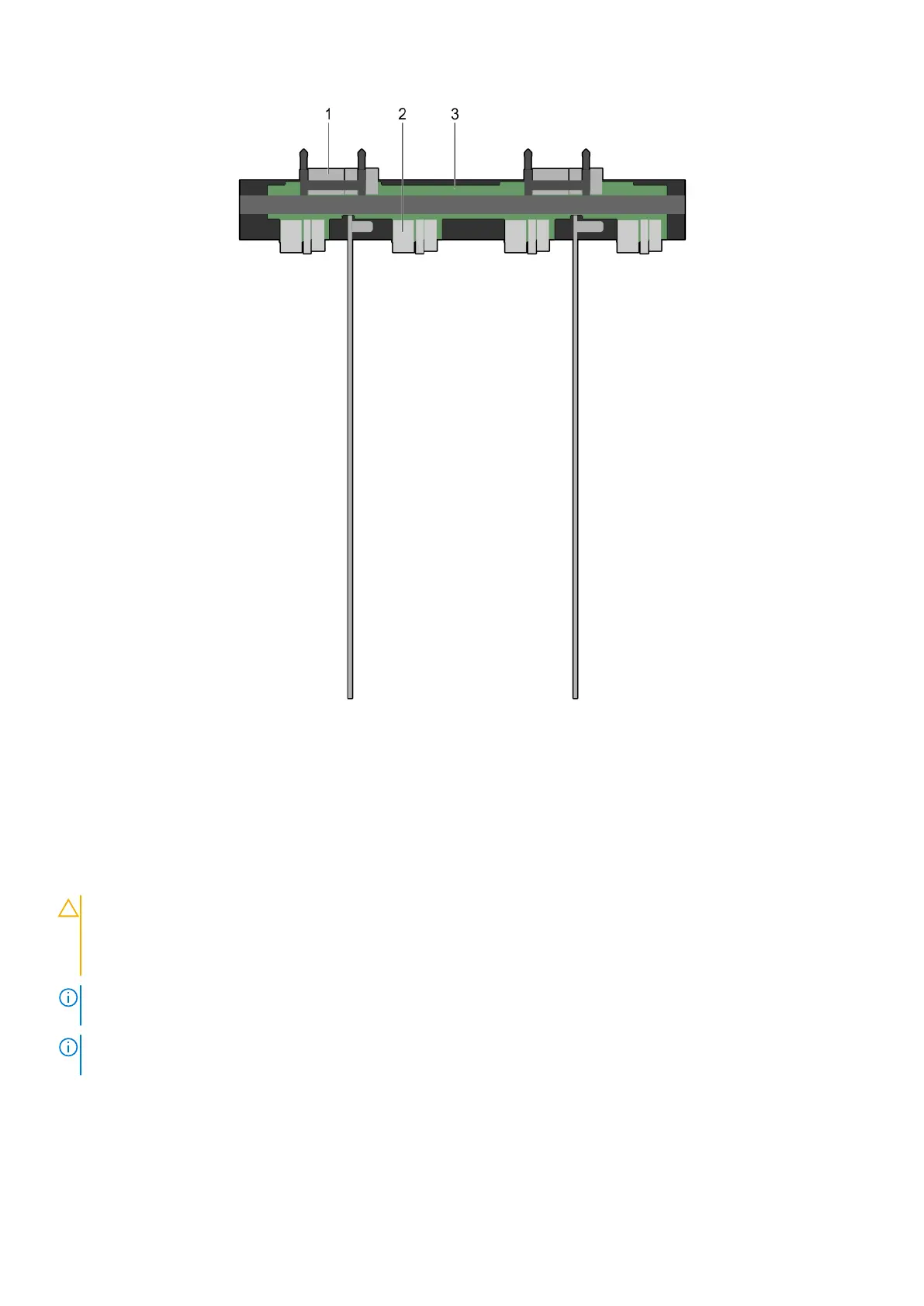
Figure 48. Top view of the interposer module
1. midplane connector (2)
2. interposer module
3. sled connector (4)
Removing the bottom interposer module
Prerequisites
CAUTION:
Many repairs may only be done by a certified service technician. You should only perform
troubleshooting and simple repairs as authorized in your product documentation, or as directed by the online or
telephone service and support team. Damage due to servicing that is not authorized by Dell is not covered by
your warranty. Read and follow the safety instructions that came with the product.
NOTE: This is a field replaceable unit (FRU). Removal and installation procedures must be performed only by Dell certified
service technicians.
NOTE: You must remove the bottom interposer module to replace a faulty module, install half-width or full-width sleds, or
service other components inside the system.
1. Ensure that you read the Safety instructions on page 33.
2. Follow the procedure listed in Before working inside your system on page 33.
3. Remove the following:
● sleds
● power supplies
Installing and removing PowerEdge FX2/FX2s enclosure components
61