Features
5 RS232/RS485 port one (configurable in the BIOS) Connect a RS232/RS485 cable to the Embedded Box PC. For
more information, see RS232/RS485 connector mapping.
6 12-26V DC power port Connect a 12-26V DC power cable for supplying power to the
Embedded Box PC. For more information about the physical
dimensions of the DC power port, see DC power port.
7 Wireless antenna port one Connect a wireless antenna to increase the range and strength of
the wireless signals.
8 Wireless antenna port two Connect a wireless antenna to increase the range and strength of
the wireless signals.
9 Remote power switch
1
Install a remote power switch.
10 RS232/RS485 port three (configurable in the
BIOS)
Connect a RS232/RS485 cable to the Embedded Box PC. For
more information, see RS232/RS485 connector mapping.
11 USB 2.0 port Connect a USB enabled device. Provides data transfer speeds up
to 480 Mbps.
12 USB 2.0 port Connect a USB enabled device. Provides data transfer speeds up
to 480 Mbps.
13 Network port two Connect an Ethernet (RJ45) cable for network access. Provides
data transfer speeds up to 10/100/1000 Mbps.
14 CANbus port (optional) Connect to a CANbus port enabled device or dongle. For more
information, see CANbus connector mapping.
15 DisplayPort Connect a monitor or another DisplayPort enabled device.
Provides video and audio output.
16 Mobile broadband antenna port two Connect a mobile broadband antenna to increase the range and
strength of the mobile broadband signals.
17 Mobile broadband antenna port one Connect a mobile broadband antenna to increase the range and
strength of the mobile broadband signals.
1 Connections made to these ports must use SELV circuits and the wire (26 AWG-18 AWG) must have Double Insulation (DI) or Reinforced Insulation (RI) to protect it from
all hazardous voltages. Torque the screws at 2.88 kg-cm (2.5 lb-in) to secure the wire to the connector.
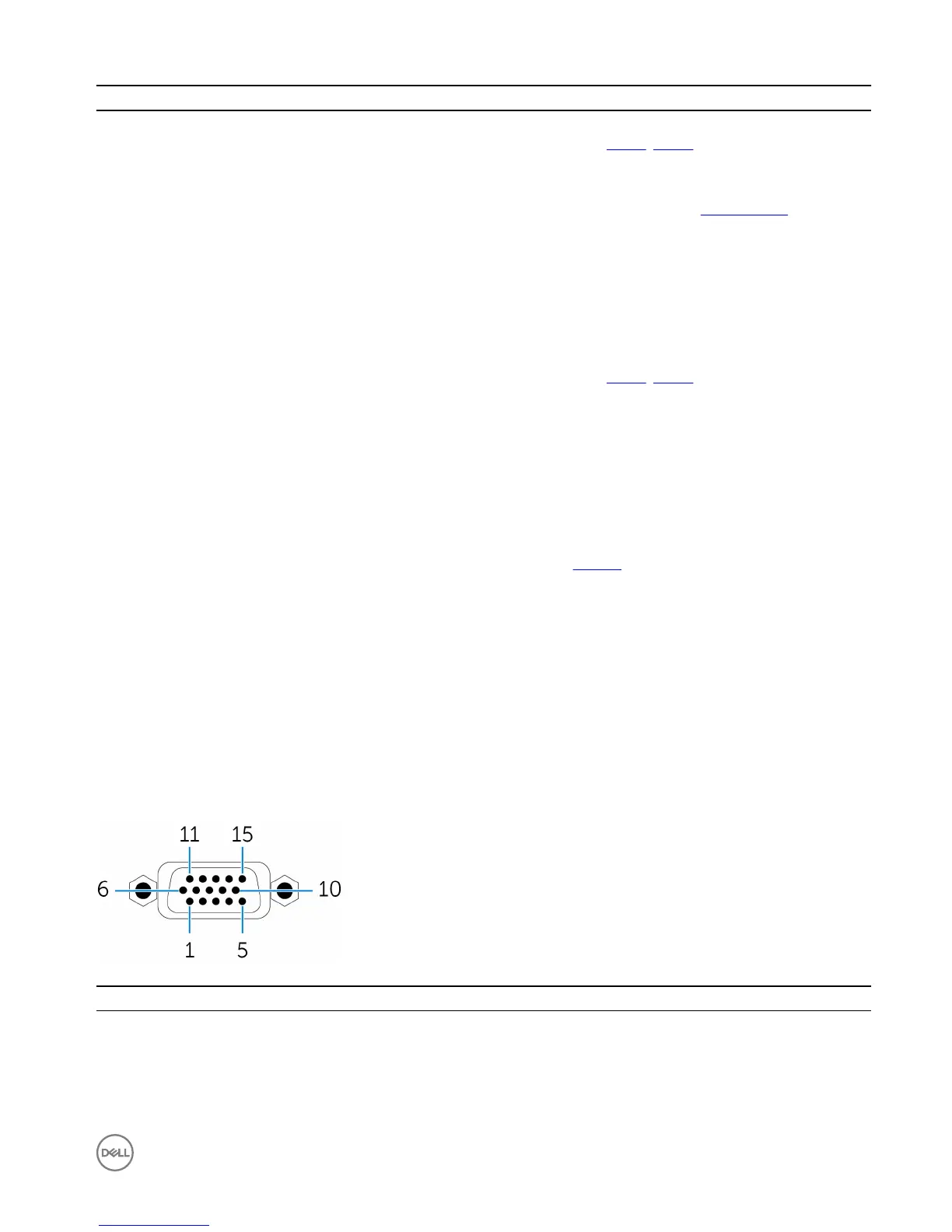
VGA connector mapping
Pin
Signal Pin Signal Pin Signal
1 RED 6 GND 11 NC
2 GREEN 7 GND 12 DDCDAT
3 BLUE 8 GND 13 HSYNC
4 NC 9 +5V 14 VSYNS
7