Getting Started Guide 9
N1124T-ON/N1124P-ON/N1148T-ON/
N1148P-ON Installation
Rack Mounting an N1124T-ON/N1124P-ON/
N1148T-ON/ N1148P-ON Switch
WARNING: Read the safety information in the
Safety and Regulatory Information
as well as the safety information for other switches that connect to or support the
switch.
The AC power connector is on the rear panel of the switch.
Installing in a Rack
WARNING: Do not use rack mounting kits to suspend the switch from under a
table or desk, or attach it to a wall.
CAUTION: Disconnect all cables from the switch before continuing. Remove all
self-adhesive pads from the underside of the switch, if they have been attached.
CAUTION: When mounting multiple switches into a rack, mount the switches
from the bottom up.
1
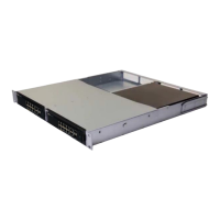
Place the supplied rack-mounting bracket on one side of the switch,
ensuring that the mounting holes on the switch line up to the mounting
holes in the rack-mounting bracket. Figure 1-3 illustrates where to mount
the brackets.
Figure 1-3. Attaching the Brackets
 Loading...