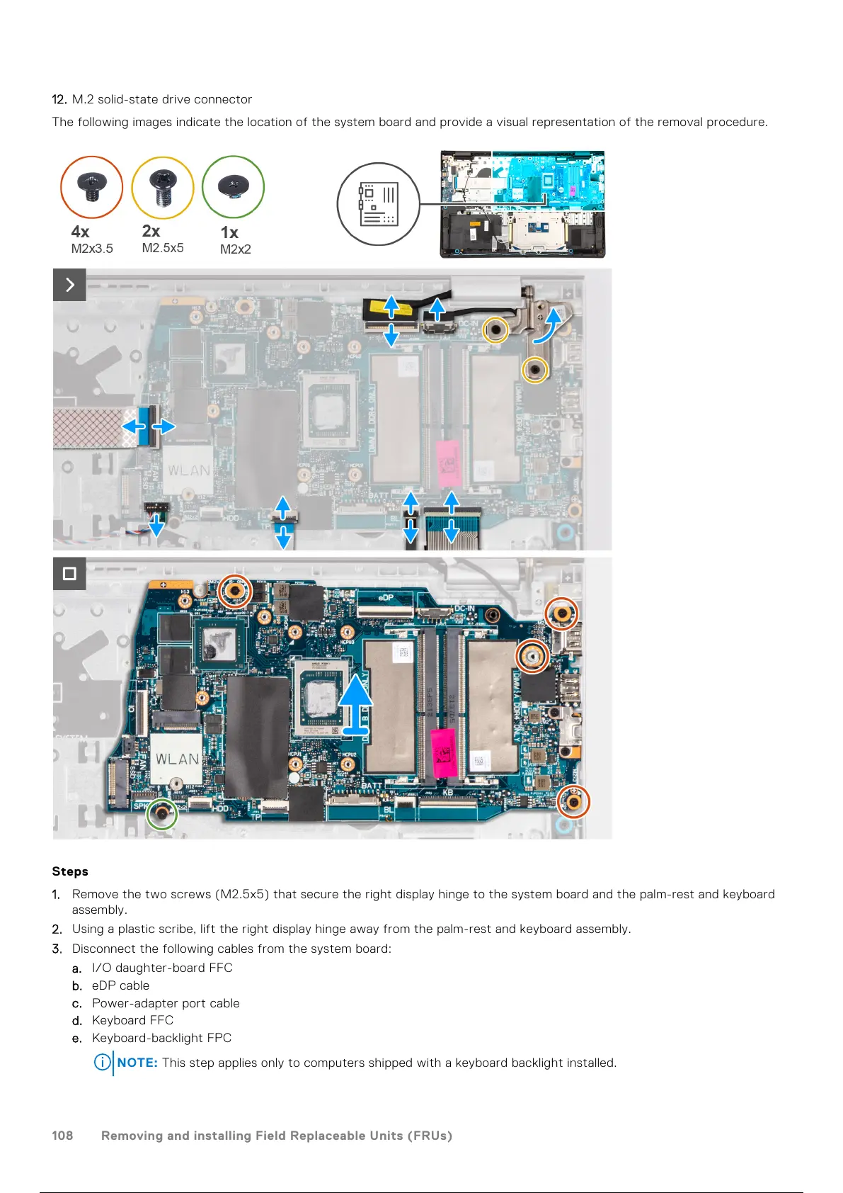
12. M.2 solid-state drive connector
The following images indicate the location of the system board and provide a visual representation of the removal procedure.
Steps
1. Remove the two screws (M2.5x5) that secure the right display hinge to the system board and the palm-rest and keyboard
assembly.
2. Using a plastic scribe, lift the right display hinge away from the palm-rest and keyboard assembly.
3. Disconnect the following cables from the system board:
a. I/O daughter-board FFC
b. eDP cable
c. Power-adapter port cable
d. Keyboard FFC
e. Keyboard-backlight FPC
NOTE: This step applies only to computers shipped with a keyboard backlight installed.
108 Removing and installing Field Replaceable Units (FRUs)
109 / 136 108 / 134 109 / 136