Steps
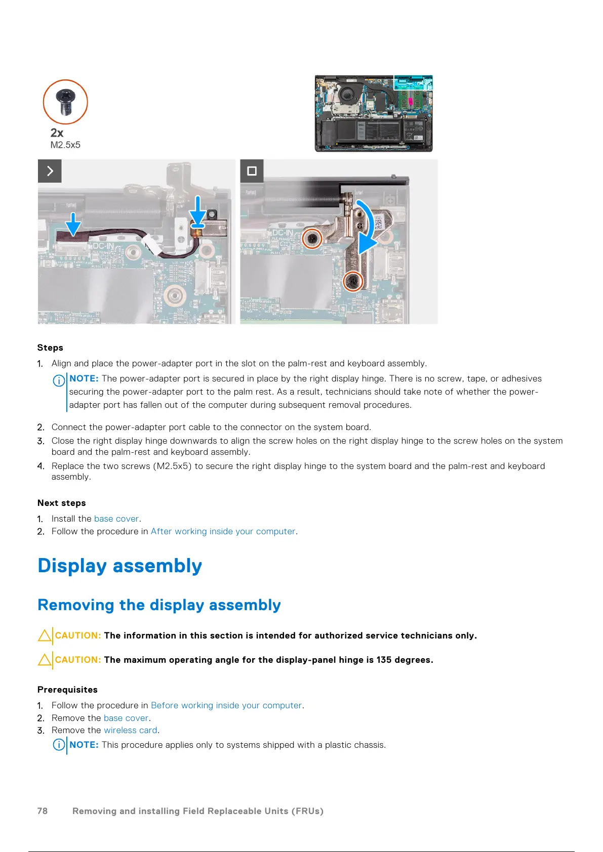
1. Align and place the power-adapter port in the slot on the palm-rest and keyboard assembly.
NOTE:
The power-adapter port is secured in place by the right display hinge. There is no screw, tape, or adhesives
securing the power-adapter port to the palm rest. As a result, technicians should take note of whether the power-
adapter port has fallen out of the computer during subsequent removal procedures.
2. Connect the power-adapter port cable to the connector on the system board.
3. Close the right display hinge downwards to align the screw holes on the right display hinge to the screw holes on the system
board and the palm-rest and keyboard assembly.
4. Replace the two screws (M2.5x5) to secure the right display hinge to the system board and the palm-rest and keyboard
assembly.
Next steps
1. Install the base cover.
2. Follow the procedure in After working inside your computer.
Display assembly
Removing the display assembly
CAUTION: The information in this section is intended for authorized service technicians only.
CAUTION: The maximum operating angle for the display-panel hinge is 135 degrees.
Prerequisites
1. Follow the procedure in Before working inside your computer.
2. Remove the base cover.
3. Remove the wireless card.
NOTE: This procedure applies only to systems shipped with a plastic chassis.
78 Removing and installing Field Replaceable Units (FRUs)
79 / 136 78 / 134 79 / 136