Removing and installing components
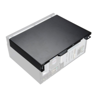
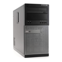
NOTE: The images in this document may differ from your computer depending on the configuration you ordered.
Recommended tools
The procedures in this document require the following tools:
● Phillips #0 screwdriver
● Phillips #1 screwdriver
● Flat headed screwdriver
● Plastic scribe
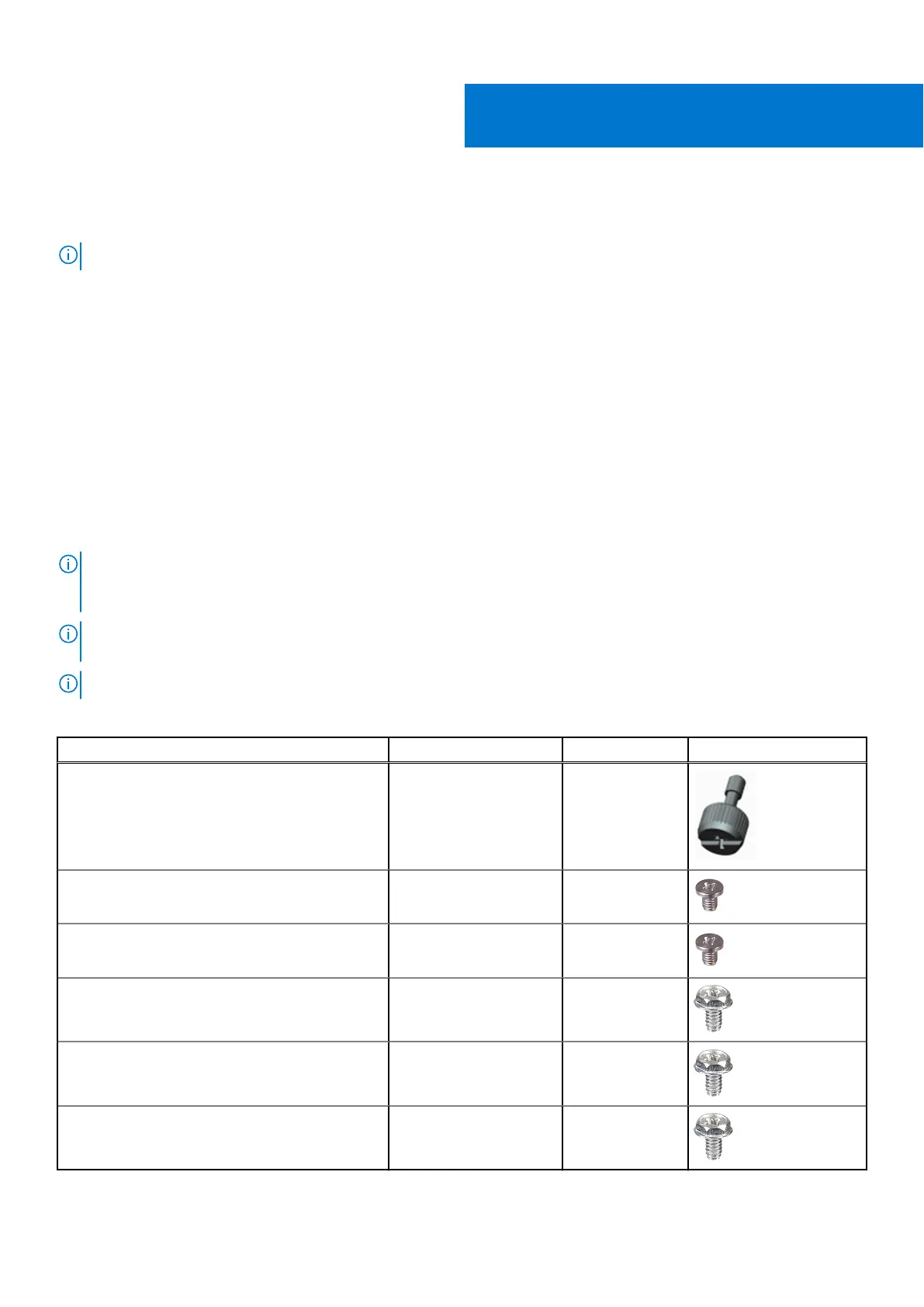
Screw List
The following table shows the screw list and the images for different components.
NOTE:
When removing screws from a component, it is recommended to note the screw type, the quantity of screws, and
then place them in a screw storage box. This is to ensure that the correct number of screws and correct screw type is
restored when the component is replaced.
NOTE: Some computers have magnetic surfaces. Ensure that the screws are not left attached to such surface when
replacing a component.
NOTE: Screw color may vary with the configuration ordered.
Table 1. Screw list
Component Screw type Quantity Image
Side cover #6-32 2
M.2 2230/2280 Solid-state drive M2x3.5 1
WLAN card M2x3.5 1
Power supply unit #6-32 3
Processor fan and heat-sink assembly #6-32 (Captive) 4
System board #6-32 11
2
10 Removing and installing components