Steps
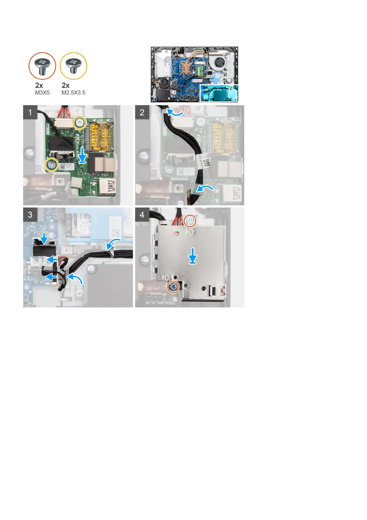
1. Align the screw holes on the side I/O-board with the screw holes on the display-assembly base.
2. Replace the two screws (M2.5x3.5) to secure the side I/O-board to the display-assembly base.
3. Route the SIO-signal cable, SIO-power cable, and audio-board cable through the routing guides on the display-assembly
base.
4. Connect the SIO-signal cable, SIO-power cable, and audio-board cable to the connectors on the system board.
5. Align the screw holes on the side I/O-board shield with the screw holes on the display-assembly base.
6. Replace the two screws (M3x5) to secure the side I/O-board shield to the display-assembly base.
Next steps
1. Install the rear-I/O bracket.
2. Install the bottom cover.
3. Install the system-board shield.
4. Install the back cover.
5. Install the cable cover (optional).
6. Install the stand.
7. Follow the procedure in After working inside your computer.
Removing and installing components
79