1. Intrusion switch connector
2. ATX CPU power connector
3. System fan connector
4. Memory module connectors
5. Power button connector
6. SD card reader connector
7. Coin-cell battery
8. System power connector
9. SATA3 connector (white)
10. SATA power cable connector
11. SATA 1connector (black)
12. Internal speaker connector
13. M.2 WLAN connector
14. SATA 2 connector (black)
15. SATA0 connector (blue)
16. M.2 PCIe SSD connector
17. Thunderbolt header
18. PCIe x16 (Slot2)
19. PCIe x1 (Slot1/2)
20. Processor socket
21. Video connector
22. Type-C connector
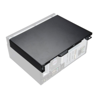
The following images indicate the location of the system board and provide a visual representation of the installation procedure.
Removing and installing Field Replaceable Units (FRUs)
99