About this task
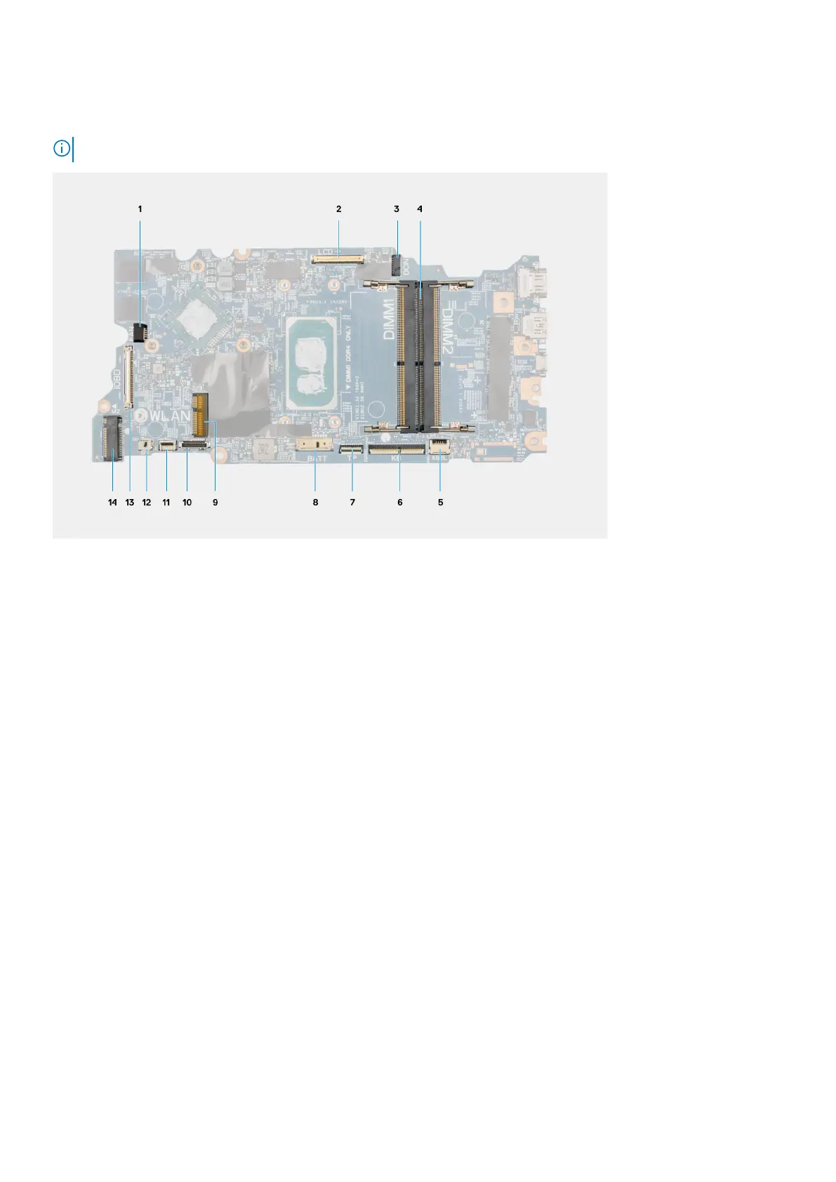
System board connectors
NOTE: The location of the memory module may vary depending on your system.
1. System fan cable connector 2. Display cable connector
3. Power adapter port connector 4. Memory module connector
5. Keyboard backlit LED cable connector 6. Keyboard cable connector
7. Touchpad cable connector 8. Battery cable connector
9. WLAN card connector 10. Hard-disk drive cable connector
11. USB cable connector 12. Speaker cable connector
13. I/O cable connector 14. M.2 SSD connector
The following images indicate the location of the system board and provide a visual representation of the removal procedure.
76
Removing and installing components