6. Remove the M.2 2230 solid state drive or M.2 2280 solid state drive (whichever applicable).
7. Remove the wireless card.
8. Remove the fan.
9. Remove the UMA heat sink or discrete heat sink (whichever applicable).
NOTE: The system board can be removed along with the heat sink.
10. Remove the plastic display assembly or aluminum display assembly (whichever applicable).
About this task
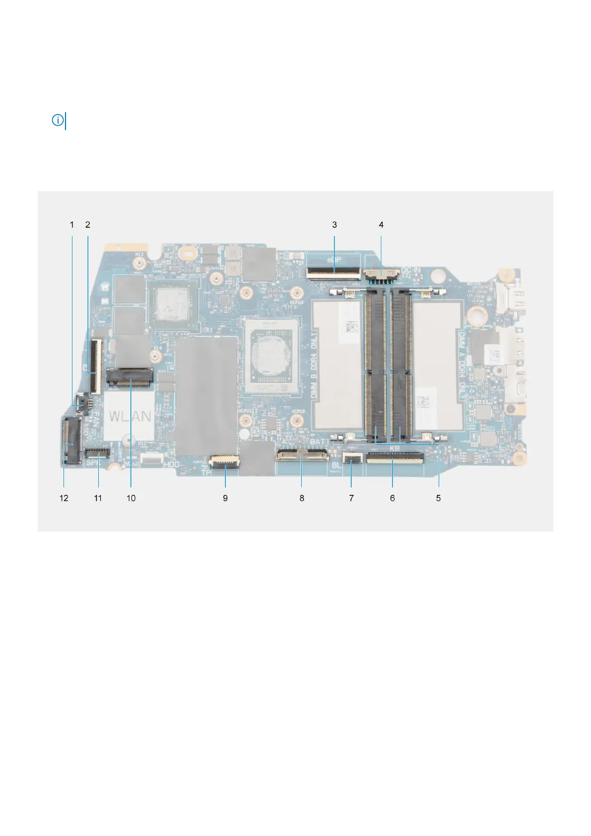
The following image indicates the connectors on your system board:
1. Fan connector 2. I/O board FFC connector
3. eDP connector 4. DC-in port connector
5. Memory modules 6. Keyboard FFC connector
7. Keyboard-backlight FFC connector 8. Battery connector
9. Touchpad FFC connector 10. Wireless connector
11. Speaker cable connector 12. Solid-state drive connector
The following images indicate the location of the system board and provide a visual representation of the removal procedure.
Removing and installing Field Replaceable Units (FRUs)
131