— 11 —
P792
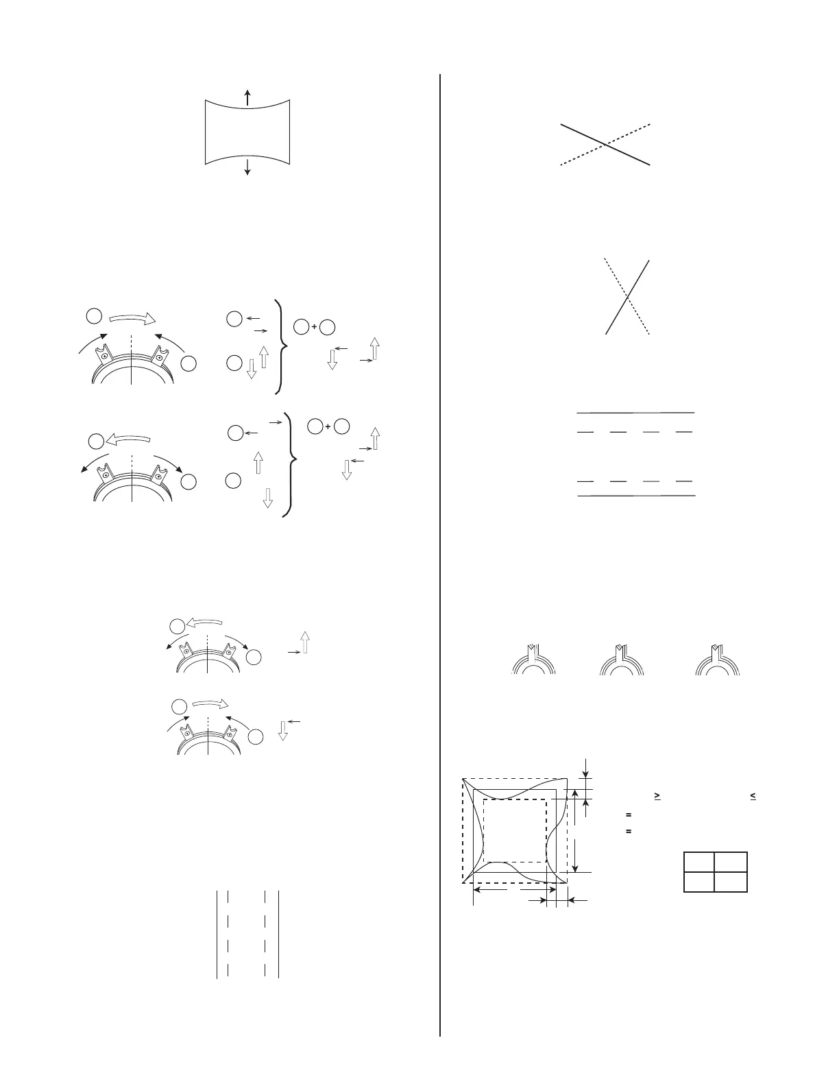
TB Pin Movement
4. Adjust V.SIZE with "VSIZE".
5. Change "CONV_SW" to "0" and "MCR2" to "153".
6. Display crosshatch pattern with red and blue lines and black fi eld.
7. Adjust H.STAT and V.STAT with 4 pole magnet. Use 4 pole magnet,
not "HSTAT" and "VSTAT".
4 Pole Magnet
1
1
1
1
1
1 2
2
2
2
2
2
R
B
R
B
R
R
R
R
B
B
B
B
8. Display crosshatch pattern with white lines and black fi eld.
9. Adjust HMC and VMC with 6 pole magnet.
6 Pole Magnet
1
2
2
1
G
G
10. Display crosshatch pattern with red and blue lines and black fi eld.
11. If necessary, repeat steps 5-8.
12. Change "CONV_SW" to "6".
13. Adjust H.TILT with TLH plate.
TLH Movement
R
BB
R
14. Adjust XCV with XCV VR.
XCV Movement
B
R
15. Adjust YCH with YCH VR.
YCH Movement
R
B
16. Adjust V.TILT with TLV VR.
TLV Movement
R
B
B
R
17. If necessary, repeat steps 3-14 to make the optimum condition for
the entire screen.
18. Fix 4-pole magnet, 6-pole magnet, TLH plate and XCV VR with
white paint.
Zero Position Neck Ass'y
Purity
4-Pole Mg
6-Pole Mg
3-5. VERTICAL AND HORIZONTAL POSITION
AND SIZE SPECIFICATION
B
b
A
a
a
b
BA
234 312
f
H
0kHz
2.0 mm
2.0 mm
f
H
60kHz
2.4 mm
2.4 mm