106 Installing System Components
b
Using a T10 Torx driver, remove the two screws that secure the display module to the system
chassis.
c
Remove the display module from the chassis cutout.
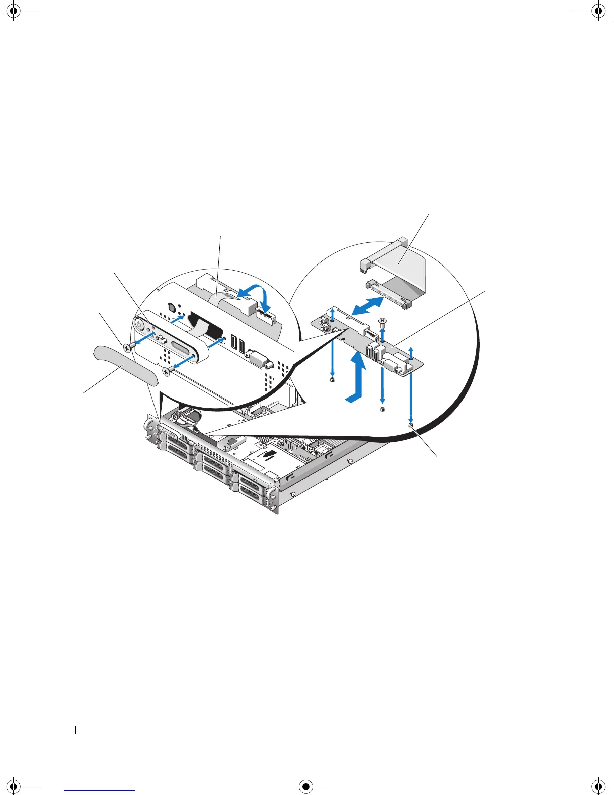
Figure 3-35. Control Panel Removal
Installing the Control Panel Assembly
1
Insert the display module into the chassis cutout and secure with the two Torx screws.
2
Affix the display module label to the display module.
3
Install the control panel board in the system chassis and secure with the three Phillips screws. See
Figure 3-35.
5
6
2
1
3
4
7
1 display module label 2 display module securing
screws (2)
3 display module
4 display module cable 5 control panel cable 6 control panel circuit board
7 control-panel circuit board
securing screws (3)
Book.book Page 106 Friday, February 3, 2006 11:09 AM

 Loading...