Dell
42
PowerEdge R210 II Technical Guide
The min-max values listed in Table 18 represent the allowable distance between the front and rear mounting
flanges in the rack. Rail depth represents the minimum depth of the rail as measured from the rack front
mounting flanges when the rail rear bracket is positioned all the way forward.
14.3 Cable Management Arm (CMA)
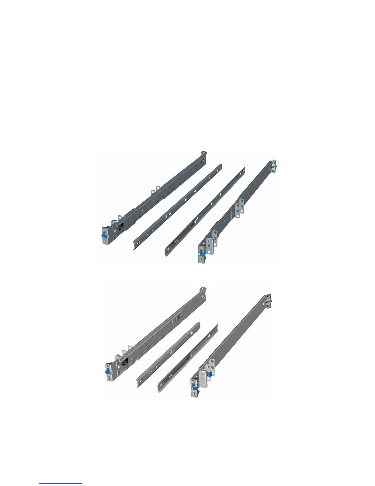
The static rails for the R210 II support a wide variety of racks and mounting configurations but do not support
the ability to extend the system out of the rack for service. Thus, they do not provide support for a cable
management arm (CMA).
14.4 Rack View
The A4 and A6 rail systems are stab-in designs, meaning that the inner (chassis) rail members must first be
attached to the sides of the system and then inserted into the outer (cabinet) members installed in the rack.
Figure 11. A4 Static Rail System
Figure 12. A6 Static Rail System

 Loading...