Do you have a question about the Dell PowerEdge R415 and is the answer not in the manual?
Lists keystrokes for accessing system features during startup.
Describes front-panel indicators, buttons, and connectors with their functions.
Explains the function of the LCD panel for system information and status.
Lists options within the Setup menu for configuring system settings.
Lists options within the View menu for displaying system information.
Explains the patterns of hard-drive indicators for drive status.
Describes back-panel connectors, buttons, and indicators.
Provides instructions for connecting external devices to the system.
Explains the indicator codes for the Network Interface Card (NIC).
Explains the indicator codes for the power supplies.
Describes the optional diagnostic indicator lights for error codes.
Explains LCD messages referring to system events and error logs.
Explains system messages that notify of potential problems.
Alerts to possible problems and prompts user response before task continuation.
Messages issued by system diagnostic utilities during system tests.
Messages generated by systems management software for system status.
Lists additional resources and documentation for system setup and support.
Specifies the boot mode (BIOS or UEFI) for operating system installation.
Details the steps to enter and navigate the System Setup program.
Lists the main categories of options available in the System Setup program.
Displays and configures system memory size, type, speed, and testing.
Displays and configures processor features like speed and cores.
Enables or disables integrated SATA controller and ports.
Specifies boot mode (BIOS/UEFI) and boot sequence.
Enables or disables integrated devices like NICs and USB ports.
Assigns IRQs to devices on the PCI bus.
Enables or disables serial ports and specifies redirection options.
Configures front-panel LCD options and user-defined strings.
Manages power usage for CPU, fans, and memory.
Configures system and setup passwords, and TPM settings.
Details how to access and use the UEFI Boot Manager for boot options.
Lists options for managing boot devices and system utilities.
Explains system and setup password features for security.
Guides on assigning, changing, and using the system password for security.
Details how to use system passwords to secure the system and protect data.
Provides steps to delete or change an existing system password.
Guides on assigning and using the setup password for System Setup access.
Explains the Lifecycle Controller for system and storage management tasks.
Details configuring, monitoring, and recovering systems remotely via BMC/iDRAC.
Describes the iDRAC6 Configuration Utility for setting parameters and managing servers.
Lists the tools required for installing system components.
Gives a general overview of the system's internal layout and safety.
Provides instructions for removing and installing the optional front bezel.
Details the procedure for opening and closing the system chassis.
Explains system support for various hard drive types and installation.
Provides steps to remove a hard-drive blank for component access.
Provides steps to install a hard-drive blank for system cooling.
Details how to remove a hard-drive carrier for drive replacement.
Explains how to remove a hard drive from its carrier.
Details how to remove a cabled hard drive from the system.
Details how to install a cabled hard drive into the system.
Explains how to remove a hard drive from its bracket.
Explains how to install a hard drive into its bracket.
Explains the function and connection of the optional optical drive.
Details the procedure to remove the optical drive from the system.
Details the procedure to install the optical drive into the system.
Lists supported power supply modules and their functionality.
Details how to remove a redundant power supply from the system.
Details how to install a redundant power supply into the system.
Explains how to remove a power supply blank for installation.
Explains how to install a power supply blank for system cooling.
Details how to remove a non-redundant power supply from the system.
Details how to install a non-redundant power supply into the system.
Provides guidelines for installing expansion cards and risers.
Details how to remove an expansion card from the system.
Details how to install an expansion card into the system.
Explains the integrated storage controller card for internal hard drives.
Details how to remove the integrated storage controller card.
Details how to install the integrated storage controller card.
Describes the expansion-card riser and its slots.
Details how to remove the expansion-card riser.
Provides steps to replace the expansion-card riser.
Explains the use of the internal USB memory key as a boot or storage device.
Explains the function of the system board shroud for airflow.
Details how to remove the system board shroud.
Details how to install the system board shroud.
Explains the function of the power distribution board shroud for airflow.
Details how to remove the power distribution board shroud.
Details how to install the power distribution board shroud.
Explains the optional iDRAC6 Express Card for remote management.
Details how to remove the optional iDRAC6 Express Card.
Details how to install the optional iDRAC6 Express Card.
Explains the optional iDRAC6 Enterprise Card for remote management.
Details how to remove the optional iDRAC6 Enterprise Card.
Details how to install the optional iDRAC6 Enterprise Card.
Explains the VFlash Media card used with the iDRAC6 Enterprise card.
Details how to remove the VFlash Media card.
Details how to install the VFlash Media card.
Describes the system's cooling fans and their importance.
Details how to remove a cooling fan from the system.
Details how to install a cooling fan into the system.
Explains the optional RAID battery for PERC controller cards.
Details how to remove the RAID battery.
Details how to install the RAID battery.
Describes supported memory types, speeds, and capacities.
Provides general guidelines for optimal system memory configuration.
Details the procedure for installing memory modules into the sockets.
Details how to remove memory modules from the system.
Explains processor installation and removal procedures.
Details how to remove a processor from the system.
Details how to install a processor into the system.
Explains the system battery and its replacement procedure.
Details how to replace the system battery.
Describes the control panel assembly, including LCD and LED modules.
Details how to remove the control panel assembly.
Details how to install the control panel assembly.
Explains the SAS backplane and its function for hard drives.
Details how to remove the SAS backplane from the system.
Details how to install the SAS backplane into the system.
Explains the power distribution board and its role in cooling.
Details how to remove the power distribution board.
Details how to replace the power distribution board.
Explains the system board and its removal procedure.
Details how to remove the system board from the chassis.
Details how to install a new system board into the chassis.
Emphasizes safety precautions for system servicing and operation.
Guides on resolving system startup failures and boot issues.
Helps diagnose and resolve issues with external device connections.
Guides on diagnosing and resolving video output problems.
Provides steps to troubleshoot issues with USB devices.
Guides on diagnosing and resolving issues with serial I/O devices.
Provides steps to troubleshoot Network Interface Card (NIC) problems.
Details procedures for handling and troubleshooting systems exposed to liquid.
Guides on troubleshooting systems that have sustained physical damage.
Guides on diagnosing and resolving issues related to the system battery.
Provides steps to diagnose and resolve power supply issues.
Guides on identifying and resolving system cooling problems.
Details how to troubleshoot issues with cooling fans.
Guides on diagnosing and resolving system memory problems.
Provides steps to troubleshoot issues with internal USB keys.
Guides on diagnosing and resolving issues with SD cards.
Guides on diagnosing and resolving issues with the optical drive.
Guides on diagnosing and resolving issues with external tape drives.
Provides steps to diagnose and resolve hard drive issues, including RAID.
Guides on diagnosing and resolving issues with storage controllers (SAS/PERC).
Guides on diagnosing and resolving issues with expansion cards.
Guides on diagnosing and resolving processor issues.
Guides on using Dell's online and embedded diagnostic tools.
Outlines the features and options available in the embedded system diagnostics.
Helps determine when to use the embedded system diagnostics for problem identification.
Explains how to select devices and options for custom diagnostic tests.
Describes how to view test results, errors, configuration, and parameters.
Details the location and settings of system board configuration jumpers.
Identifies and describes the system board connectors for various components.
Identifies and describes the SAS backplane board connectors.
Details components of the PCIe expansion-card riser and its buses.
Identifies and describes the connectors on the power distribution board.
Provides steps to disable system and setup passwords if forgotten.
Details contact methods for Dell sales, technical support, and customer service.
| Processor cache | 6 MB |
|---|---|
| Processor cores | 4 |
| System bus rate | 6.4 GT/s |
| Processor family | AMD Opteron |
| Processor socket | Socket C32 |
| Motherboard chipset | - |
| Processor frequency | 2.8 GHz |
| Processor cache type | Smart Cache |
| Processor boost frequency | 3.2 GHz |
| Number of processors installed | 1 |
| HDD size | - \ |
| HDD capacity | 500 GB |
| RAID support | Yes |
| HDD interface | Serial ATA |
| Optical drive type | DVD±RW |
| Total storage capacity | 1000 GB |
| Maximum storage capacity | 12 TB |
| Number of HDDs installed | 2 |
| Memory slots | 8 |
| Internal memory | 4 GB |
| Memory clock speed | 1333 MHz |
| Internal memory type | DDR3-SDRAM |
| Maximum internal memory | - GB |
| Maximum graphics card memory | 8 MB |
| Graphics card | G200eW |
| Graphics card family | Matrox |
| LAN controller | Broadcom BCM5716 |
| Cabling technology | 10/100/1000Base-T(X) |
| Ethernet interface type | Gigabit Ethernet |
| USB 2.0 ports quantity | USB 2.0 ports have a data transmission speed of 480 Mbps, and are backwards compatible with USB 1.1 ports. You can connect all kinds of peripheral devices to them. |
| Compatible operating systems | Microsoft Windows Server 2012 Microsoft Windows Server 2012 Essentials Microsoft Windows Small Business Server 2011 Microsoft Windows Small Business Server 2008 Microsoft Windows Server 2008 SP2, x86/x64 (x64 includes Hyper-V) Microsoft Windows Server 2008 R2 SP1, x64 (includes Hyper-V v2) Microsoft Window HPC Server 2008 Novell SUSE Linux Enterprise Server Red Hat Enterprise Linux |
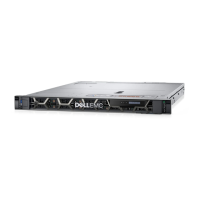
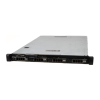
| Chassis type | Rack (1U) |
| Width | - mm |
|---|