Do you have a question about the Dell PowerStore 500T and is the answer not in the manual?
Provides links to product and feature documentation or release notes.
Provides links for information about products, software updates, licensing, and service.
Provides information on how to contact support and open a service request.
Determines the placement of the new base enclosure within the rack.
Verifies all base enclosure components are received from the shipping package.
Confirms all necessary equipment for installing the new base enclosure is received.
Describes the procedure to install one rail in the cabinet.
Details lifting and sliding the enclosure onto the rails to secure it in the rack.
Refers to the PowerStore Networking Guide for switch cabling information.
Guides on plugging power cables into the base enclosure power supply and PDU.
Guides on discovering the newly installed enclosure after installation.
Recommends upgrading to the latest PowerStore software version.
Procedures to remove a faulted drive and install a replacement.
Identifies and locates a faulted drive using PowerStore Manager.
Steps to remove a 2.5" drive with a blinking amber LED.
Steps to align, push, and secure a new 2.5" drive into its slot.
Checks if the replacement drive status reads 'Healthy' in PowerStore Manager.
Instructions for packaging and shipping defective parts back to the service provider.
Actions to add a new drive to the base enclosure.
Steps to unlock and remove the front bezel from the enclosure.
Steps to insert a finger and pull out a drive filler module.
Checks if the added drive status reads 'Healthy' in PowerStore Manager.
Procedures to remove a faulted power supply and install a replacement.
Identifies and locates a faulted power supply using PowerStore Manager.
Explains the LEDs on the base enclosure power supply and their states.
Steps to remove a power supply from the node.
Steps to align and push a new power supply into the node until it clicks.
Checks if the replacement power supply status reads 'Healthy'.
Procedures to remove and install a replacement 4-port card.
Precautionary steps before replacing a 4-port card.
Identifies and locates a faulted 4-port card using PowerStore Manager.
Explains the LEDs on the embedded module for identifying faulted parts.
Instructions to power down the node as described in Power control procedures.
Procedure to remove a node from the chassis.
Steps to slide and lift the top cover off the node.
Steps to remove SFPs and push blue tabs to release the 4-port card.
Steps to align the 4-port card and its pegs with the embedded module slots.
Steps to position and pull the cover forward to secure it.
Steps to align pins and slide the node into the chassis.
Instructions to power up the node as described in Power control procedures.
Checks if the replacement 4-port card status reads 'Healthy'.
Procedures to remove a faulted SFP and install a replacement SFP.
Identifies and locates a faulted SFP module using PowerStore Manager.
Steps to disconnect cable, pull latch, and remove the SFP module.
Steps to verify part number and push the new SFP module into the port.
Checks if the replacement SFP module status reads 'Healthy'.
Procedures to remove a faulted I/O module and install a replacement.
Precautionary steps before replacing an I/O module.
Identifies and locates a faulted I/O module using PowerStore Manager.
Explains the LEDs on the base enclosure I/O module.
Steps to pull the trigger and gently pull the I/O module from the slot.
Steps to align, push, and lock the new I/O module into the slot.
Checks if the replacement I/O module status reads 'Healthy'.
Procedures to remove a faulted fan module and install a replacement.
Precautionary steps before replacing a fan module.
Identifies and locates a faulted fan module using PowerStore Manager.
Steps to slide and lift the top cover off the node.
Steps to disconnect the fan module power cable from the motherboard.
Steps to place, squeeze, and connect the fan module.
Steps to position and pull the top cover forward to secure it.
Steps to align pins and slide the node into the chassis.
Checks if the replacement fan module status reads 'Healthy'.
Procedures to remove a faulted DIMM and install a replacement.
Precautionary steps before replacing a DIMM.
Identifies and locates a faulted DIMM using PowerStore Manager.
Steps to locate and remove a faulted DIMM from the node.
Steps to align and vertically insert the DIMM into the socket.
Procedures to remove a faulted M.2 boot module and install a replacement.
Precautionary steps before replacing an M.2 boot module.
Identifies and locates a faulted M.2 boot module using PowerStore Manager.
Ensures connection to the peer node is working correctly before replacement.
Steps to pull the tab and lift the M.2 boot module from the motherboard.
Steps to place and connect the M.2 boot module into the slot.
Runs the svc_repair command to reimage the internal M.2 boot module.
Checks if the replacement M.2 boot module status reads 'Healthy'.
General procedures and precautions for removing, installing, and storing replaceable units.
Procedures to prevent equipment damage from electrostatic discharge.
Precautions to reduce ESD risk when an ESD kit is not available.
Explains unit acclimation to the operating environment before applying power.
Precautions for removing, handling, and storing replaceable units.
Best practices for unpacking a part, including ESD precautions.
Notes to consider before powering down or up nodes, appliances, or clusters.
Lists procedures for powering off a PowerStore node.
Steps to power off a node using the PowerStore Manager interface.
Steps to power off a node using a service script via SSH.
Lists procedures for powering on a PowerStore node.
Steps to power on a node using a service script via SSH.
Steps to power on a node by reseating it in the chassis.
Lists procedures for rebooting a PowerStore node.
Steps to reboot a node using the PowerStore Manager interface.
Steps to reboot a node using a service script via SSH.
Lists procedures for powering off PowerStore appliances.
Steps to power off a single PowerStore T model appliance.
Steps to power on a PowerStore T model appliance.
Lists procedures for powering off a PowerStore cluster.
Steps to power off a PowerStore T model cluster.
Lists procedures for powering on a PowerStore cluster.
Steps to power on a PowerStore T model cluster.
Explains how to collect support materials for troubleshooting.
Steps to select, start, and monitor a support materials collection job.
Steps to disable support notifications before performing maintenance.
Steps to enable support notifications after finishing servicing.
Resets the system to original, default factory settings using service scripts.
| Model | PowerStore 500T |
|---|---|
| Category | Storage |
| Maximum Drives | 96 |
| Processor | Dual Intel Xeon Scalable processors |
| Form Factor | 2U |
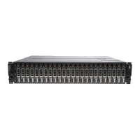
| Base Enclosure Drives | Up to 25 |
| NVMe over Fabrics (NVMe-oF) | Yes |
| Max Drives | 96 |
| Redundancy | Yes |
| Operating System | PowerStoreOS |
| Drive Bays | 25 |
| Network Connectivity | 10/25 GbE |
| Data Services | Deduplication, Compression, Thin Provisioning, Snapshots, Replication |
| Drive Types Supported | NVMe SSD |
| Networking | 10/25 GbE |
| Protocols | FC, iSCSI |
| Power Supply | Dual, hot-pluggable |
| Management | PowerStore Manager |