Table 4. QSFP28 port LEDs for 2x50 GbE mode
LED Description
Link LED
• O—No link.
• Solid green—Port link is 2x50 GbE.
Activity LED
• O—No link
• Flashing amber, ~30 ms—Port link is 2x50 GbE.
Table 5. SFP+ port LEDs
LED Description
Link LED
• O—No link.
• Solid green—Link operating at maximum port speed.
• Solid amber—Link operating at lower speed.
Activity LED
• O—No link.
• Flashing green, ~30 ms—port activity.
• Flashing amber, ~30 ms—port activity.
Prerequisites
The following is a list of components required for successful installation of the Z9100-ON:
NOTE
: Detailed installation instructions for the Z9100-ON are provided in Site Preparations and Install the Z9100-ON.
• Z9100–ON chassis, or multiple chassis if stacking
• AC or DC country- and regional-specic cables to connect the AC or DC power source to each of the chassis’ AC or DC power supplies
• ReadyRail™ mounting brackets for rack installation, included
• Screws for rack installation
• #1 and #2 Phillips screw drivers, not included
• Ground cable screws for L-bracket, included
• Copper and ber cables
Other optional components are:
• Ground cable screw, M3 or M4 depending on your system
• Extra mounting brackets
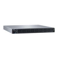
Z9100–ON congurations
You can order the Z9100–ON system in several congurations.
You can order the following supported hardware components:
• Z9100–ON AC or DC Normal Airow: thirty–two 10/25/40/50/100 GbE ports with two SFP+ 10 GbE ports, two AC or DC power
supply and ve fan subsystems. Airow is from the I/O side to the power supply side.
• Z9100–ON AC or DC Reverse Airow: thirty–two 10/25/40/50/100 GbE ports with two SFP+ 10 GbE ports, two AC or DC power
supply and ve fan subsystems. Airow from the power supply side to the I/O side.
• Fan with airow from the I/O side to the PSU side—normal airow
The Z9100–ON system
11
 Loading...