Delta Controls
Document Edition 4.2 Page 25 of 43
Sequence of Operation
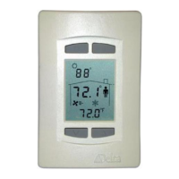
The current damper position is generated from the Cooling Minimum setpoint, Cooling Maximum
Setpoint and the Cool 1 value.
Damper Position
Max
Damper
Position
Min
Damper
Position
Controller Output (Cooling 1)
0
Max Damper Position
0% 100%
For the DNT-T103 the desired damper position is compared to the current estimated damper position by
the Tri-State controller loop. The Tri-State damper outputs (1 & 2) are used to control the damper and
adjust the estimated position to match the current desired position. The rate of the damper from closed
to open is adjusted using AV24 – Damper Run Time (seconds). The default value is 120 seconds. On
the DNT-T221, the analog damper output 1 is used to control damper position, but also requires a
runtime value set in AV24.
In Unoccupied Deadband mode the damper position is set to zero.
Output 3 may be selected as a fan, which would operate according to the above table. Alternatively, the
output may be selected to be Heating 1 or supplementary cooling 2, which may be of type Binary or
PWM or Timed Proportional. Also refer to page 15 for operating information on Box Mode and
Controller Operation.
4. HEAT PUMP UNIT (HPU) – [Application (AV12) = 3]
Function: Control of a single-stage Heat Pump Unit with reversing valve and optional fan.
DNT-T103 I/O (Outputs 1 to 3 are Triacs)