Do you have a question about the DELTA DORE DRIVER 620 and is the answer not in the manual?
Select between weekly or daily programming modes.
Set programming increments to 1-hour, 30-minute, or 15-minute intervals.
Enable or disable user modification of programmed settings.
Adjust the displayed temperature by +/- 5°C in 0.1°C increments.
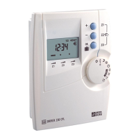
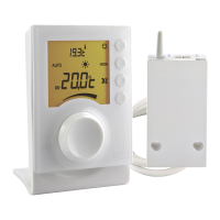
The Delta Dore Driver 610 - 620 is a sophisticated pilot wire programmer designed for controlling heating systems across one or two zones. This device allows users to manage their home's heating with precision, offering both basic and advanced configuration options to suit various needs and preferences. Its primary function is to regulate convectors by sending pilot wire signals, ensuring efficient and comfortable temperature management within the designated zones.
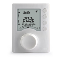
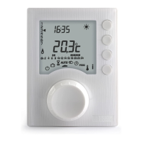
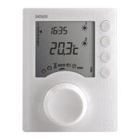
The Driver 610 - 620 serves as a central control unit for pilot wire heating systems. It enables users to program heating schedules, set desired temperatures, and monitor the system's status. The device features a clear digital display that shows the current time, temperature, and operational mode. Through its intuitive interface, users can navigate various menus to configure the system according to their lifestyle.
For the Driver 610, the device manages a single heating zone, controlling convectors connected to its terminal 3. The Driver 620 extends this capability to two zones, with terminal 3 controlling convectors in zone 1 and terminal 4 controlling convectors in zone 2. This dual-zone functionality allows for more granular control over heating in different areas of a home, potentially leading to greater energy efficiency and personalized comfort.
The core functionality revolves around programming heating schedules. Users can define specific time slots and associated heating modes (e.g., Comfort, Eco, Frost Protection) for each day of the week. This ensures that heating is active only when needed, optimizing energy consumption. The device supports different programming increments, such as hourly, 30-minute, or 15-minute intervals, providing flexibility in schedule creation.
A crucial aspect of the device's operation is its ability to perform self-checks on pilot wire connections. Upon initial power-up or during a dedicated test mode, the Driver 610 - 620 verifies that the convectors are correctly wired. This diagnostic feature helps identify and troubleshoot connection issues, ensuring the system operates as intended. If a problem is detected, the display will show an error code, guiding the user or technician to the source of the issue.
The device also incorporates a clock backup mechanism, which retains time settings for a limited period in the event of a power outage. This prevents the need for immediate reprogramming after a brief power interruption, enhancing user convenience.
The Driver 610 - 620 is designed for ease of use, with a combination of a selector dial and push buttons for navigation and setting adjustments. The installation process is straightforward, involving mounting the unit at an accessible height (approximately 1.5 m) and connecting the pilot wires to the appropriate terminals. The casing can be easily separated from its base for wiring, and the terminal box cover is designed to stay open during installation.
Setting the time is one of the first steps after installation. This is done by turning the selector dial to the clock icon, which makes the days flash. Users then use the '+' and '-' buttons to adjust the day, followed by the 'OK' button to confirm and move to setting the hour and minutes. This sequential process ensures accurate timekeeping, which is fundamental for programmed heating schedules.
Basic configurations are accessed by turning the selector dial to the 'AUTO' position and holding the 'i' button for 5 seconds. This menu allows users to select the programming type (weekly or daily) and the programming increments (1-hour, 30-minute, or 15-minute). These choices directly impact how detailed and flexible the heating schedules can be. After each configuration, the unit returns to the menu selection, allowing users to adjust multiple settings in one session.
Advanced configurations provide more granular control over the system. By turning the selector dial to the 'PROG' position and holding the 'i' button for 5 seconds, users can access settings such as program modification authorization and temperature correction. The program modification authorization feature allows users to enable or disable the ability to change heating programs, which can be useful in multi-user environments or to prevent accidental changes.
The temperature correction feature is particularly useful for ensuring accurate temperature readings. If there's a discrepancy between the temperature displayed by the unit and the actual room temperature (measured with a thermometer), users can adjust the displayed temperature in increments of 0.1°C. This calibration ensures that the heating system responds accurately to the desired comfort levels, compensating for any minor sensor inaccuracies or local environmental factors.
The device also includes a test mode for checking pilot wire connections. This mode is initiated by turning the selector dial to the 'AUTO' position and pressing the 'OK' button. The unit will then display 'Pb' followed by the output number being tested. Users can launch tests for individual outputs, and the display will indicate whether the connection is correct or incorrect. This diagnostic tool is invaluable for installers and users alike, helping to quickly identify and resolve wiring issues.
While the Driver 610 - 620 is designed for reliable operation, it also includes features that facilitate maintenance and troubleshooting. The self-diagnostic capabilities, particularly the pilot wire connection test, are a primary maintenance feature. By displaying 'Pb' and indicating incorrect connections, the device guides users to specific wiring problems, simplifying the troubleshooting process. This reduces the need for specialized tools or extensive electrical knowledge to diagnose common installation errors.
In the event of a fault, the device provides clear indicators. If the 'i' symbol flashes, it signifies a detected fault in the installation, prompting the user to press the 'i' button to view the specific fault details. If the display shows 'dEF' followed by a number, it indicates a fault within the unit itself that requires professional attention, suggesting a return to after-sales service. These clear error messages help users understand the nature of the problem and determine the appropriate course of action.
The device also offers a reset function, allowing users to restore factory settings for each of the configuration menus. This is useful for troubleshooting persistent issues, starting fresh with configurations, or preparing the unit for a new user. The reset process involves turning the selector dial to the 'U' position and holding the 'i' button for 5 seconds, then confirming the reset for specific menus. This ensures that users can revert to a known good state without having to manually reconfigure every setting.
For general maintenance, the device is designed to be robust and durable, with a protection index of IP 30, indicating protection against solid objects larger than 2.5 mm and no protection against liquids. This suggests that the unit should be installed in an environment with normal pollution levels and protected from direct exposure to water or excessive dust.
The design of the unit, with its easily separable base and accessible terminal box, also aids in maintenance. Should there be a need to re-check wiring or replace the unit, the physical access points are designed for convenience. However, users are explicitly advised not to attempt repairs themselves and to contact after-sales service for any internal issues, ensuring safety and proper functioning of the device.
The comprehensive manual provided with the device serves as a vital maintenance tool, offering detailed instructions for installation, configuration, and troubleshooting. It emphasizes the importance of adhering to current standards (e.g., NF C15-100) and good practices during installation and operation, which are crucial for the long-term reliability and safety of the heating system.
| Operating Temperature | 0°C to +40°C |
|---|---|
| Storage Temperature | -10°C to +50°C |
| Radio Frequency | 868 MHz |
| Accuracy | ±0.5°C |
| Display | LCD |
| Communication | Wired |
| Compatibility | Delta Dore systems |
| Power Supply | 230V |
| Temperature Range | 5°C to 30°C |