This document provides comprehensive instructions for the installation, operation, and maintenance of the Delta Dore TYBOX 137, 237, and 337 series of thermostats. It covers various aspects from initial setup to advanced programming and troubleshooting, ensuring users can effectively manage their heating systems.
Function Description
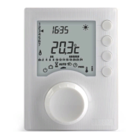
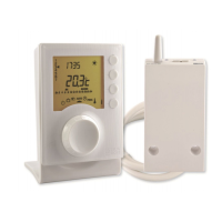
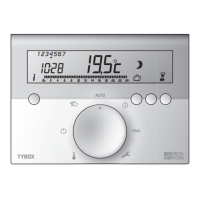
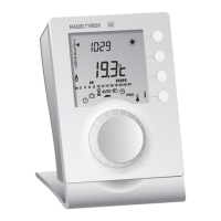
The Delta Dore TYBOX series thermostats are designed to control heating systems, offering precise temperature regulation and programmable scheduling. These devices act as central control units for managing comfort and energy efficiency within a home or building. The TYBOX 337 model includes an outdoor sensor, allowing for more sophisticated temperature management based on external conditions, which is crucial for features like anticipation (OPTIM and OPTIM+).
The core function of these thermostats is to switch heating circuits on or off based on user-defined set-point temperatures and programmed schedules. They receive temperature readings from internal sensors (and an external sensor for TYBOX 337) and compare them with the desired settings. When the room temperature falls below the set-point, the thermostat signals the heating system (e.g., boiler, circulator pump) to activate. Conversely, when the temperature reaches or exceeds the set-point, the heating system is turned off.
The TYBOX series supports different programming modes:
- Daily programming (PROG x1): Allows for a single program to be set for all days of the week.
- 5+2 daily programs (PROG 5+2): Enables separate programs for weekdays (5 days) and weekends (2 days).
- Weekly programming (PROG x7): Offers individual programming for each day of the week, providing maximum flexibility.
The thermostats also feature a "Frost Protection" mode, which maintains a minimum temperature to prevent pipes from freezing, and an "Economy" mode for reduced heating when the space is unoccupied or during specific times.
Usage Features
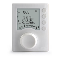
The TYBOX thermostats are designed for user-friendly interaction, featuring a clear display and intuitive controls.
Installation:
- Outdoor Sensor (TYBOX 337 only): The outdoor sensor must be installed vertically on a north or north-west facing wall, away from direct sunlight, heat sources (chimneys, air vents), and thermal bridges. This placement ensures accurate external temperature readings. Activation involves setting two internal switches to "ON" after opening the sensor cover.
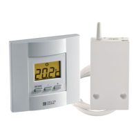
- Receiver: The receiver, which communicates with the thermostat and controls the heating system, can be mounted using screws or double-sided adhesive. It should be positioned near the heating control (burner or boiler thermostat input) and away from metallic parts to ensure optimal radio transmission. The receiver's relay can be configured for "Normally Open" (NO) or "Normally Closed" (NC) operation, and its direction can be changed by pressing a button for 10 seconds.
Basic Operation:
- Time Setting: The time and date are set by turning the selector dial to the appropriate mode, then using the + or - buttons to adjust values and the OK button to confirm.
- Programming Modes: Users can select their preferred programming type (PROG x1, PROG 5+2, PROG x7) using a switch on the device.
- Temperature Adjustment: The desired temperature can be easily adjusted using the + and - buttons.
- Program Stage Length: In Menu 1 (1-02), users can define the length of a program stage (e.g., 60, 30, or 15 minutes), which dictates how long a specific heating setting will remain active.
- Comfort Temperature Regulation: For systems with thermostatic valves, the TYBOX primarily regulates Economy and Frost-Protection temperatures, with comfort temperature set on individual radiators or convectors (Menu 1, 1-08).
- Anti-seizing Function: The thermostat can activate an anti-seizing function for the circulator pump (1 minute every 24 hours) to prevent it from seizing up due to inactivity (Menu 1, 1-09).
Advanced Features:
- Measured Temperature Correction: Users can calibrate the displayed temperature if it differs from the actual room temperature (Menu 2, 2-02).
- Temperature Display Mode: The display can show either the continuous temperature setting or the room temperature (Menu 2, 2-04).
- Control Time Base: For "on/off" type settings, the control time base can be adjusted (15, 30, 45, or 60 minutes), and hysteresis (differential) can be set via Menu 2-11 (Menu 2, 2-08).
- Optimisation (TYBOX 337): This feature anticipates reaching the desired temperature at the programmed time, taking into account the outside temperature. OPTIM+ adds automatic correction based on historical data (auto-adapt). The history can be reset via Menu 2-16 (Menu 2, 2-15).
- Automatic Time Change: The thermostat can automatically adjust for summer/winter time changes (Menu 2, 2-06).
- Boiler Maintenance Reminder: Users can set a reminder for boiler maintenance (0 to 365 days) (Menu 2, 2-07).
- Permission to Change Programme and Settings: Access to program and setting modifications can be restricted (Menu 2, 2-01).
- Transmitter Presence: The system can detect the presence of a transmitter (Menu 2, 2-12).
Maintenance Features
The TYBOX series includes features to ensure longevity and ease of maintenance.
Battery Replacement:
- When the battery symbol appears on the display, users have approximately one month to replace the batteries. The devices use 2 x 1.5V LR03 (AAA alkaline) batteries.
- It is crucial to replace the batteries within approximately 30 seconds to avoid resetting the time settings. If the time setting is lost, it will need to be reprogrammed.
Restoring Factory Settings:
- Factory settings can be restored for individual menus (Menu 1, Menu 2, RF settings) by navigating to the desired menu, turning the selector dial, and pressing the 'i' button for 5 seconds, then confirming with OK. This is useful for troubleshooting or reconfiguring the device.
Product Association:
- The products (thermostat and receiver) are pre-associated at the factory.
- If re-association is needed (e.g., after a reset or adding a new product), the process involves pressing a button on the receiver for 3 seconds until its LED flashes, then pressing the 'i' button on the transmitter for 5 seconds. The system also allows for associating other home automation radio products.
Boiler Operating Time Meter:
- The thermostat can track the boiler's operating time. This meter can be reset via Menu 2-17, which is useful for maintenance scheduling and tracking boiler usage.
History Reset for Optimisation:
- For models with the OPTIM+ feature, the historical data used for auto-adaptation can be reset via Menu 2-16. This might be necessary if the heating system or environment changes significantly.
Overall, the Delta Dore TYBOX 137, 237, and 337 thermostats offer a robust solution for heating control, combining ease of use with advanced programming and maintenance capabilities to enhance comfort and energy efficiency.