REMOTE PROGRAMMING SM3300
24 / 30 DELTA ELEKTRONIKA B.V. rev. Jan. 2022
Change the password to block the unit.
The default password is "depower".
Passwords are not case sensitive.
In case of a forgotten password see next chapter Trouble
Shooting.
Unit documentation in PDF-format available:
- Safety instructions.
- Unit operation and installation manual.
- Interfaces operation and installation manual.
- Ethernet & Sequencer programming manual.
7.3
The ETH interface is available 40s after start up of the unit.
Connect the unit to the network via the LAN-connector at the
rear side, see fig 7 - 3.
Download the programming manual for Ethernet & Sequencer
via the web interface or via www.DeltaPowerSupplies.com.
Set the programming source for voltage, current and/or power
to 'eth' via the front menu or the web interface.
7.4
Download the programming manual for Ethernet & Sequencer
via the web interface or via www.DeltaPowerSupplies.com.
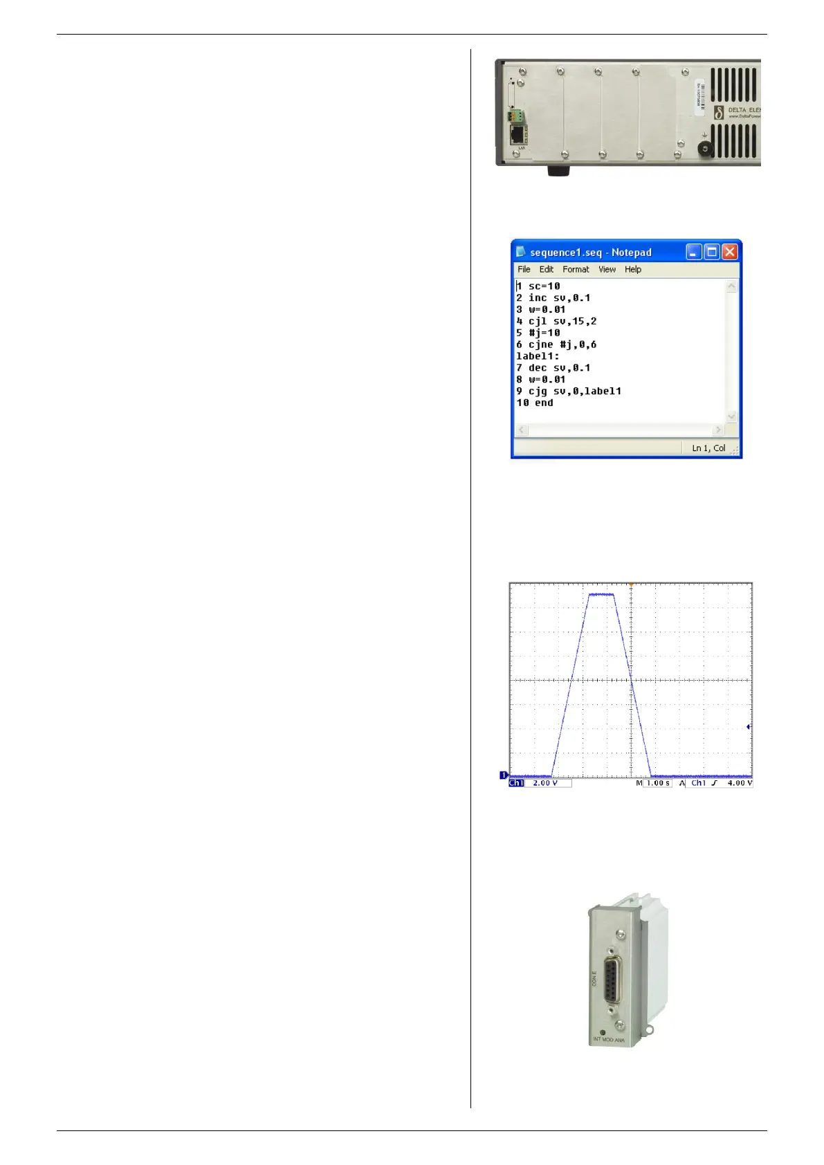
Define a sequence using a basic text editor, for example
Notepad. Save as "filename.seq". An example is shown in
fig. 7 - 4 and fig. 7 - 5.
Upload the sequence to the unit via the web interface or via
Eth programming commands.
Set the programming source for voltage, current and/or power
to 'seq' via the front menu, the web interface or Eth
commands.
Start/Stop the sequence via the web interface, Eth commands
or a hardware trigger via the Digital I/O interface.
Note: copy the uploaded sequences into the non-volatile
memory before switching off the unit. Standard they are
uploaded in the volatile memory and are lost after switching
off the mains.
7.5
Set the programming source for voltage and/or current to
'slot1...4' via the front menu, the web interface or Eth
commands.
The following interfaces can be plugged in the slots at the
rear panel of the unit. There is room to insert a total of 4
interfaces (see fig. 7 - 6 ... 11).
7.5.1 ISOLATED ANALOG PROGRAMMING
With this interface it is possible to program the CV- and CC-
settings using a 0 - 5V or 0 - 10V voltage source.
The CV- and CC-monitor signals can be measured with a volt
meter (0 - 5V or 0.10V). Also available are the 5V logic status
signals, Remote ShutDown (RSD = 5V), an auxiliary voltage
(+12V) and a reference of 5.1V.
Because the interface is isolated from the power output, earth
loops between the programming source and the power supply
are prevented.
All connections are pin compatible with other Delta
Elektronika power supplies such as ES150, SM800, SM1500,
SM6000 etc.
Note1: analog interface can NOT be inserted in slot1.
Note2: maximum 1 analog interface possible per unit.
See datasheet and manual of the INT MOD ANA for more
information.
7.5.2 SERIAL & USB PROGRAMMING
The protocols RS232, RS422, RS485 and USB (Virtual COM)
are supported by this interface.
With this interface it is possible to program the CV- and CC-
settings, to read the CV- and CC-monitor values and the
internal status signals. See datasheet and manual of the INT
MOD SER for more information.
fig 7 - 3
The location of the LAN-connector and the available
interface slots at the rear panel.
fig 7 - 5
Output voltage as result of the above example..
fig 7 - 4
Example of a small sequence to ramp up the output to
15V and then back to 0V.
fig 7 - 6
Isolated Analog interface
 Loading...


