REMOTE PROGRAMMING SM3300
25 / 30 DELTA ELEKTRONIKA B.V. rev. Jan. 2022
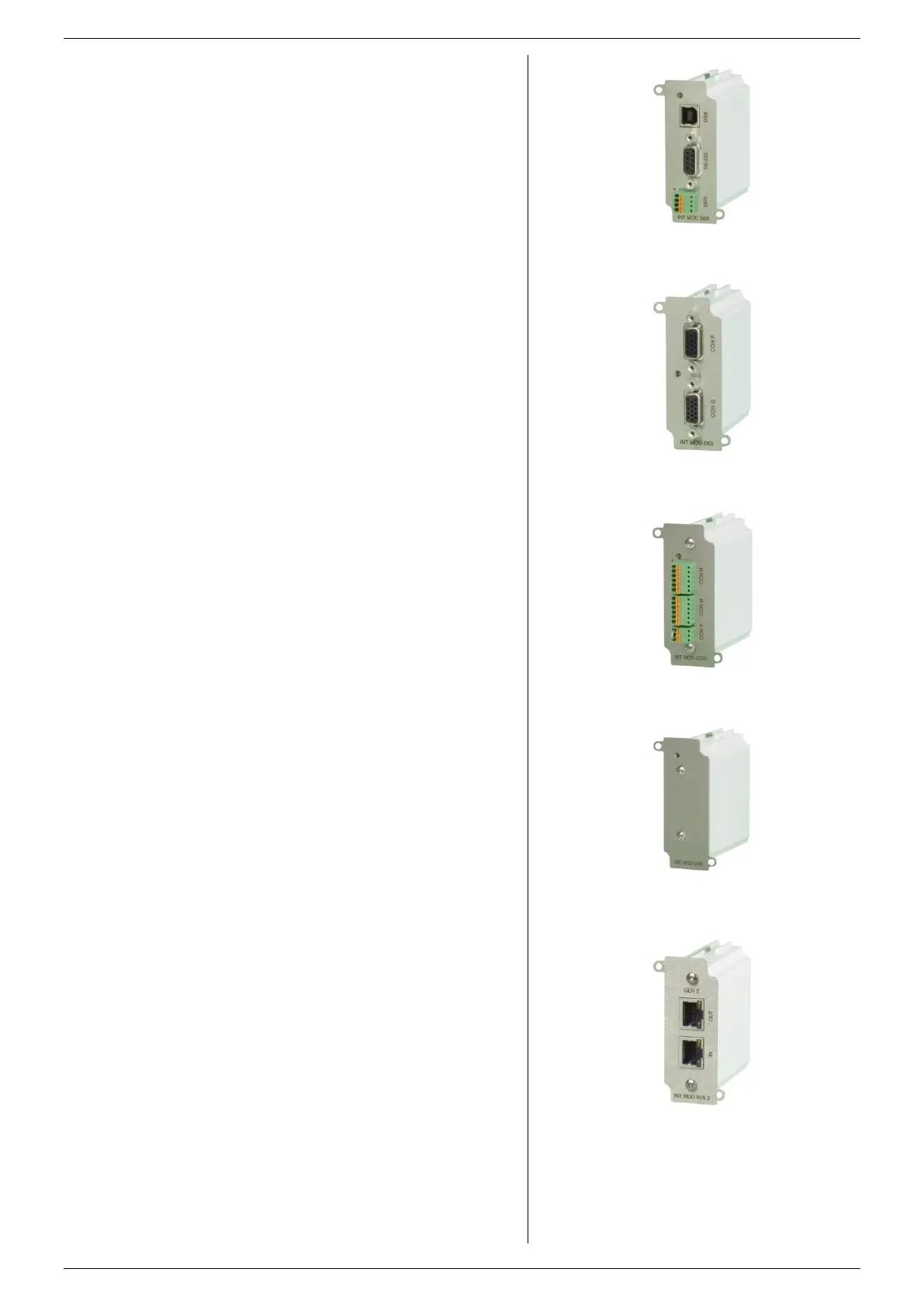
fig 7 - 9
Isolated Contacts
This interface provides 8 opto-isolated logic inputs and 8
opto-isolated logic open drain outputs.
All in- and outputs have a common zero.
See datasheet and manual of the INT MOD DIG for more
information.
On this interface, there are 4 floating relay contacts available
that can be controlled by Ethernet commands.
This can be used to trigger an external safety alarm or to
interact in automated processes.
Floating Interlock connector (standard Interlock is at the level
of Safety Earth).
Floating Enable input to switch the output On/Off (24Vdc).
See datasheet and manual of the INT MOD CON for more
information.
Note: the floating relay contacts can not be controlled by the
sequencer.
With this interface it is possible to perform several
simulations.
One of these simulation modes is photovoltaic simulation
based upon user variables.
Other simulation modes are internal resistance, leadless
sensing and fold current simulation.
All modes are easy configurable through the web interface.
Note1: simulation interface can NOT be inserted in slot1.
Note2: maximum 1 simulation interface possible per unit.
Note3: this interface cannot be combined with a master slave
interface.
See datasheet and manual of the IND MOD SIM for more
information.
7.5.6 MASTER / SLAVE CONTROL
The resulting combination behaves like one power supply and
can be manually controlled or programmed on the master.
Mixed parallel - series operation is also possible.
Note1: maximum 1 master slave interface possible per unit.
Note2: this interface cannot be combined with a simulation
interface.
See datasheet and manual of the IND MOD M/S for more
information.
fig 7- 8
Digital I/O Module.
fig 7 - 7
Serial & USB Programming Module.
fig 7 - 11
Master Slave interface M/S.
Note: the M/S can only be used in sm3300,
the INT MOD M/S-2 only in the SM15K
fig 7 - 10
Simulation interface
 Loading...


