7
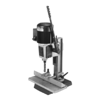
Fig. 9
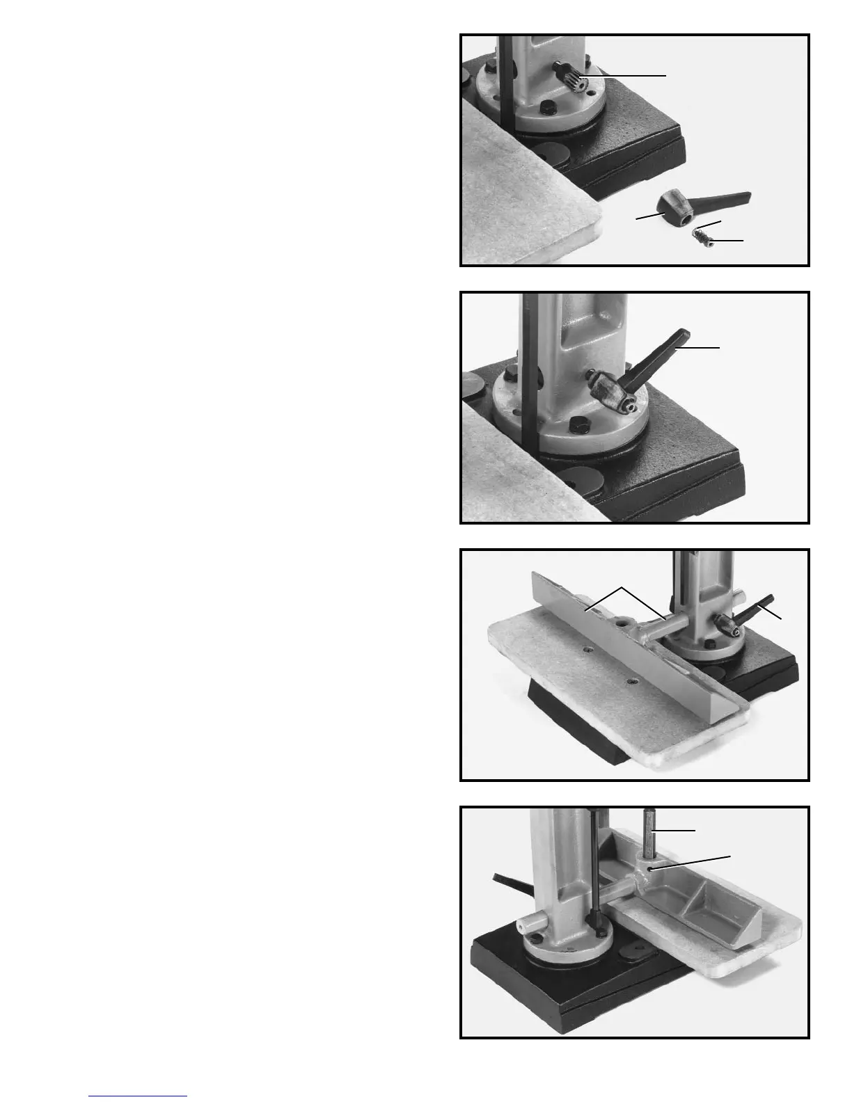
Fig. 10
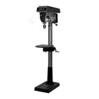
Fig. 11
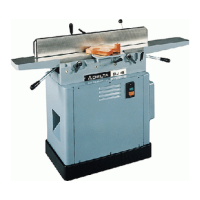
Fig. 12
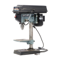
2. Thread stud (D) Fig. 9, into hole on side of column,
as shown. Do not thread stud (D) all the way into hole at
this time.
3. Reassemble handle (C) Fig. 9, on stud (D) and re-
place screw (A) and spring (B).
4. Fig. 10 illustrates the handle assembly (C) assembled
to the column.
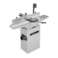
5. Insert bar of fence assembly (E) Fig. 11, through
hole in column as shown. Tighten handle (C) against flat
on fence bar to hold fence in position. NOTE: Handle (C)
is spring-loaded and can be repositioned on the stud
located underneath the handle by pulling out the handle
and repositioning it on the stud.
6. Insert bar (F) Fig. 12, into hole on top of fence as
shown, and tighten set screw (G) against flat on bar (F).
D
C
B
A
C
C
E
F
G