3
Disconnect the machine from the power source.
THE FOLLOWING INSTRUCTIONS ARE FOR THE DELTA 15" UTILITY DRILL PRESSES.
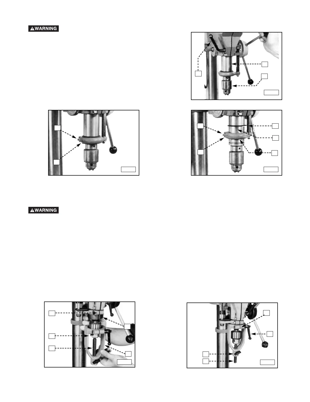
1. Lower the spindle (A) Fig. 7 approximately 3" and lock the quill
(B) in position by turning the locking lever (C) clockwise.
2. Loosen the set screw (D) Fig. 8 and the hex nut (E).
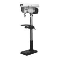
3. Slide the rubber ring (F) Fig. 9 up on the quill and raise the
stop collar (G) approximately 7/8". Tighten the set screw (D)
Fig. 8 and the hex nut (E) just enough to hold the stop collar
(G) in position.
THE FOLLOWING INSTRUCTIONS ARE FOR THE DELTA 15" UTILITY DRILL PRESSES AND DELTA 16-1/2"
VARIABLE SPEED DRILL PRESS.
Fig. 7
Fig. 8
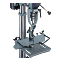
1. Install and lock the smaller diameter end of the alignment pin (H) in the spindle (A) Fig. 10.
2. Install the largest inside diameter split-ring bushings (J) Fig. 10 around the quill and under the stop collar (G).
3. While holding the split-ring bushings (J) Fig. 10 in position on the quill, slide the chisel holder (K) over the align-
ment pin (H) and over the split-ring bushings (J).
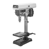
IMPORTANT: Before tightening the locking lever (L) Fig. 11, align the slot in the split-ring bushings (J) Fig. 10 with the
slot in the chisel holder (K) Fig. 11. Tighten the thumb screw (M) on the alignment pin (H). Tighten the locking lever
(L) around the split ring bushings.
NOTE: The locking lever is spring-loaded. Change it by pulling out and repositioning the hub of the lever on the nut
located directly under the hub.
4. After the chisel holder (K) Fig. 11 is installed on the machine, loosen the thumb screw (M) and remove the align-
ment pin (H) from the spindle.
5. After successfully completing these instructions, go to the section in this manual entitled “ATTACHING THE
FENCE TO THE TABLE.”
Fig. 10
Disconnect the machine from the power source.
Fig. 9
Fig. 11
C
B
A
E
D
E
D
F
B
G
J
K
A
H
G
K
L
M
H