15
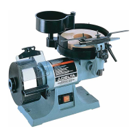
Fig. 40
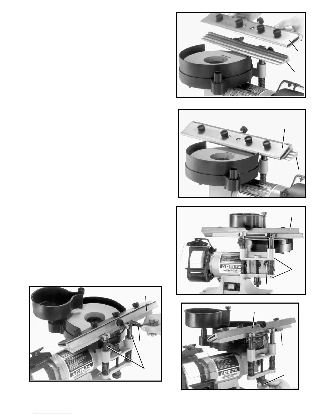
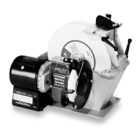
Fig. 41
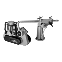
Fig. 42
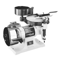
Fig. 43
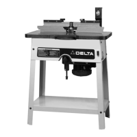
5. Fig. 41, illustrates sliding tool rest (K) in position on
tool rest base (J).
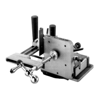
4. Place sliding tool rest (K) Fig. 40, in position on base
(J).
Fig. 44
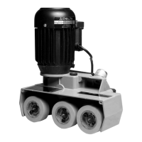
6. To level sliding tool rest (K) Fig. 42, with the wet grind-
ing wheel, loosen screw (L), rotate complete tool rest
base (E) right or left until tool rest (K) is level with the
wet grinding wheel and tighten screw (L).
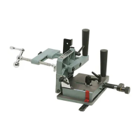
7. To raise sliding tool rest (K) Fig. 43, unlock two posts
(M) by moving clamp lever (N) to the right, as shown.
Rotate knob (O) Fig. 44, clockwise to raise, or coun-
terclockwise to lower the tool rest (K). After the height
of tool rest (K) is set, move clamp lever (N) to the left
in the locked position.
K
J
K
J
K
E
L
K
N
M
K
N
O