18
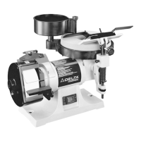
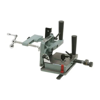
7. Check to see if the bevel edge of the knife (B) Fig. 56,
is flat on the grinding wheel. If an adjustment is nec-
essary, turn tilting screw (O) Fig. 56, until the edge of
the knife is flat on the grinding wheel.
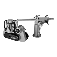
8. Fig. 57, illustrates a typical grind ing operation of a
jointer or planer knife.
Fig. 53
Fig. 54
Fig. 55
Fig. 57
Fig. 56
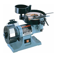
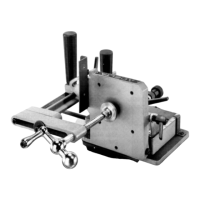
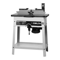
4. Adjust the height of tool rest base (H) Fig. 54, by
moving locking lever (J) to the right and turning rais-
ing and lowering knob (K) until knife (B) Fig. 53, lightly
touches grinding wheel (L). Then move locking lever
(J) Fig. 54 to the left to lock in place.
5. Check to see if the knife (B) Fig. 53, is parallel with
grinding wheel (L) at both ends when the knife is just
contacting the wheel.
3. Place sliding tool rest (G) Fig. 53, onto the tool rest
base (H) as shown.
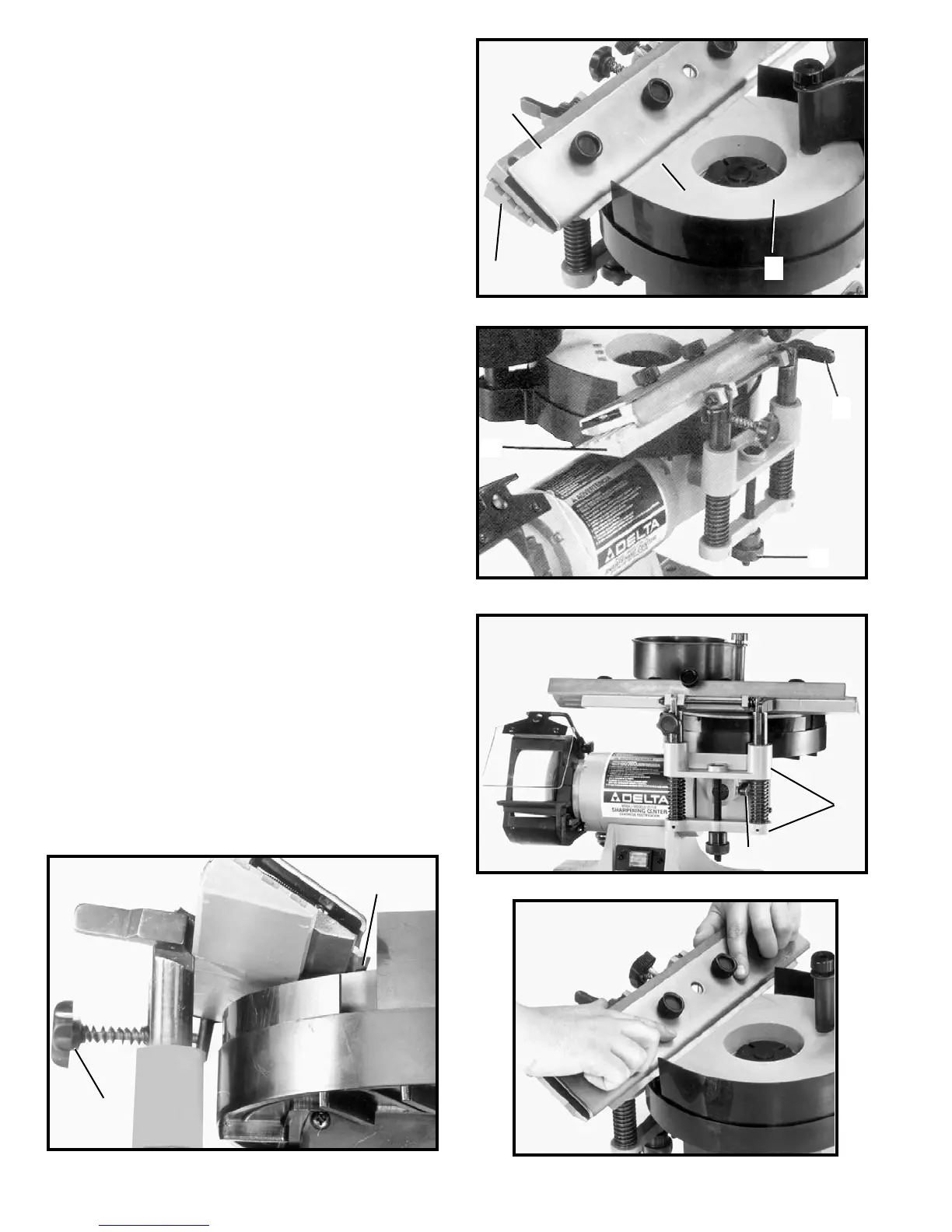
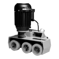
6. If the knife (B) Fig. 53, is not parallel with the grind-
ing wheel, loosen screw (M) Fig. 55, and rotate tool
rest base (N) until knife is parallel with grinding wheel.
Then tighten screw (M) Fig. 55.
B
O
M
N
G
H
B
L
H
J
K