10
Fig. 14
Fig. 15
ASSEMBLING FENCE
TO MACHINE
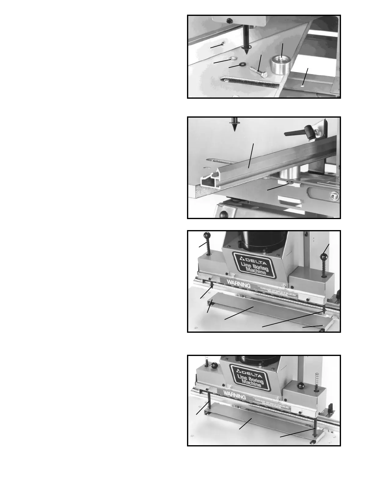
1. Place spacer (A) Fig. 14, over hole (B) in table
bracket with large countersunk end of spacer (A) in the
up position.
2. Place a 1/4" lockwasher (C) Fig. 14, and a 1/4" flat
washer (D) on the 1/4-20x1-1/2" hex head screw (E) and
insert screw (E) up through hole (B) in table bracket and
through hole in spacer (A). Thread screw (E) into
threaded hole (F) on bottom of fence. NOTE: DO NOT
TIGHTEN HARDWARE AT THIS TIME.
3. Assemble remaining spacer to opposite end of fence
in the same manner.
4. Figure 15 illustrates the fence (G) assembled to the
table bracket. NOTE: Do not completely tighten the two
screws, one of which is shown at (E), at this time.
F
D
C
E
A
G
E
B
Fig. 16
Fig. 17
ALIGNING FENCE PARALLEL
TO LINE BORING HEAD
1. Set the right fence stop to 9 inches on the fence
scale and the left fence stop should be moved out
beyond the 9 inch mark. Position gage (A) Fig. 16, on
table as shown, with points of both indexing pins (B) over
holes (C) in gage.
2. Unscrew and remove knobs (D) Fig. 16, from top of
indexing pins.
3. Allow indexing pins (B) Fig. 17, to lower until points
of indexing pins engage the two holes in gage (A) as
shown.
D
D
B
B
A
C
C
B
B
A
 Loading...