4
ASSEMBLY INSTRUCTIONS
The table and table locking handle are furnished dis-
assembled from the scroll saw to prevent damage dur-
ing shipment.
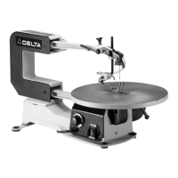
1. To assemble the table (A) Fig. 2, to the machine, find
the two special screws (B) and two locknuts (C).
Fig. 2
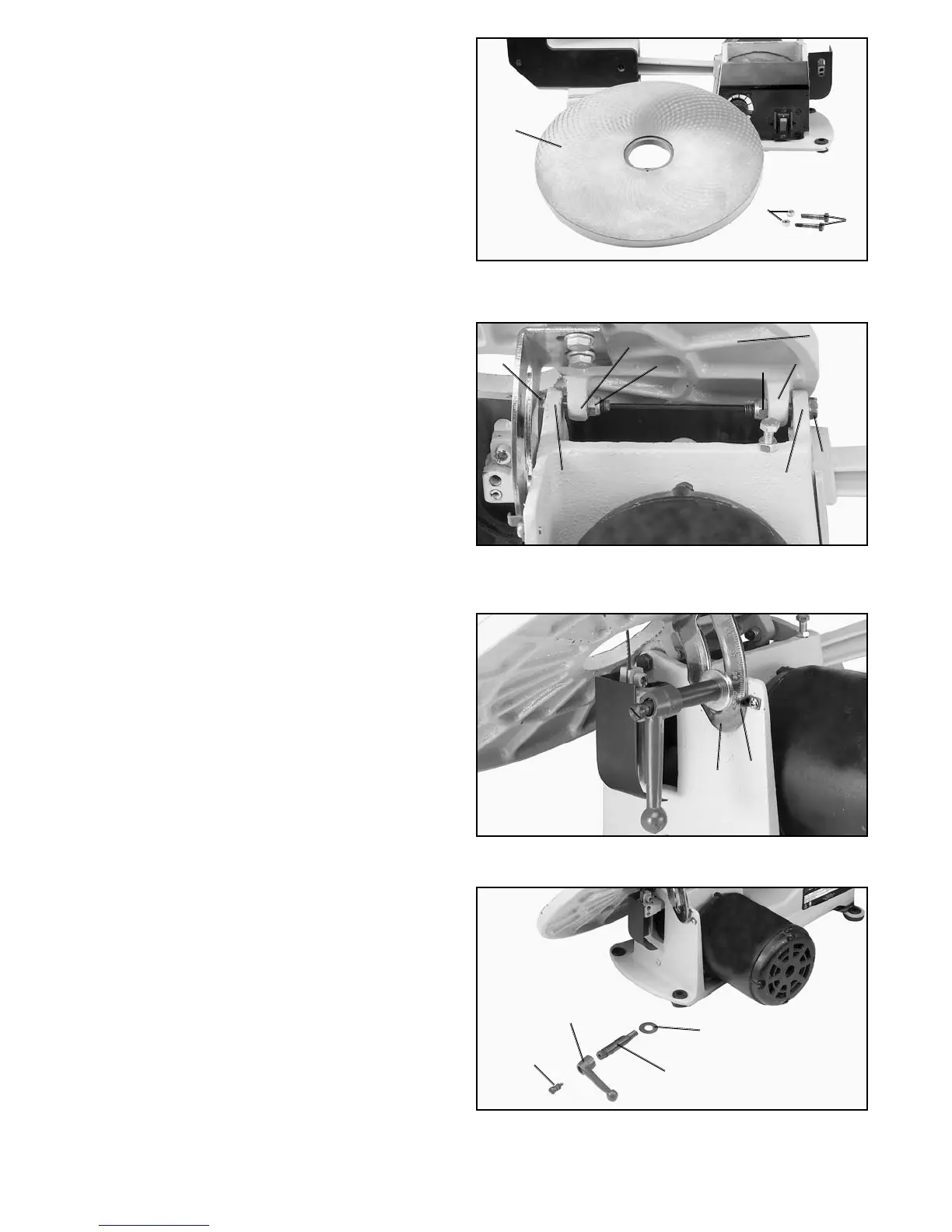
Fig. 3
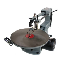
Fig. 4
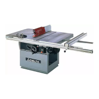
Fig. 5
2. Position table (A) Fig. 3, on the machine as shown.
Align the two holes in the table trunnions (0) with the two
holes in the base (P) of the machine and fasten the table
(A) to the base (P) using the two special screws (B) and
locknuts (C) as shown. NOTE: Before tightening the spe-
cial screws (B) and nuts (C) make sure the angle of tilt
scale (D) Fig. 4, is positioned inside pointer (E) as shown.
Also, do not completey tighten the special screws (B)
and nuts (C) Fig. 3. Table must be able to tilt freely.
3. To facilitate assembly of table lock knob assembly,
remove screw and spring (F) Fig. 5, and handle (G) from
stud (H). Place washer (J) on threaded end of stud (H).
A
C
B
B
P
O
C
A
C
O
B
P
D
E
F
G
H
J