6
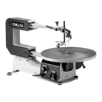
Fig. 10
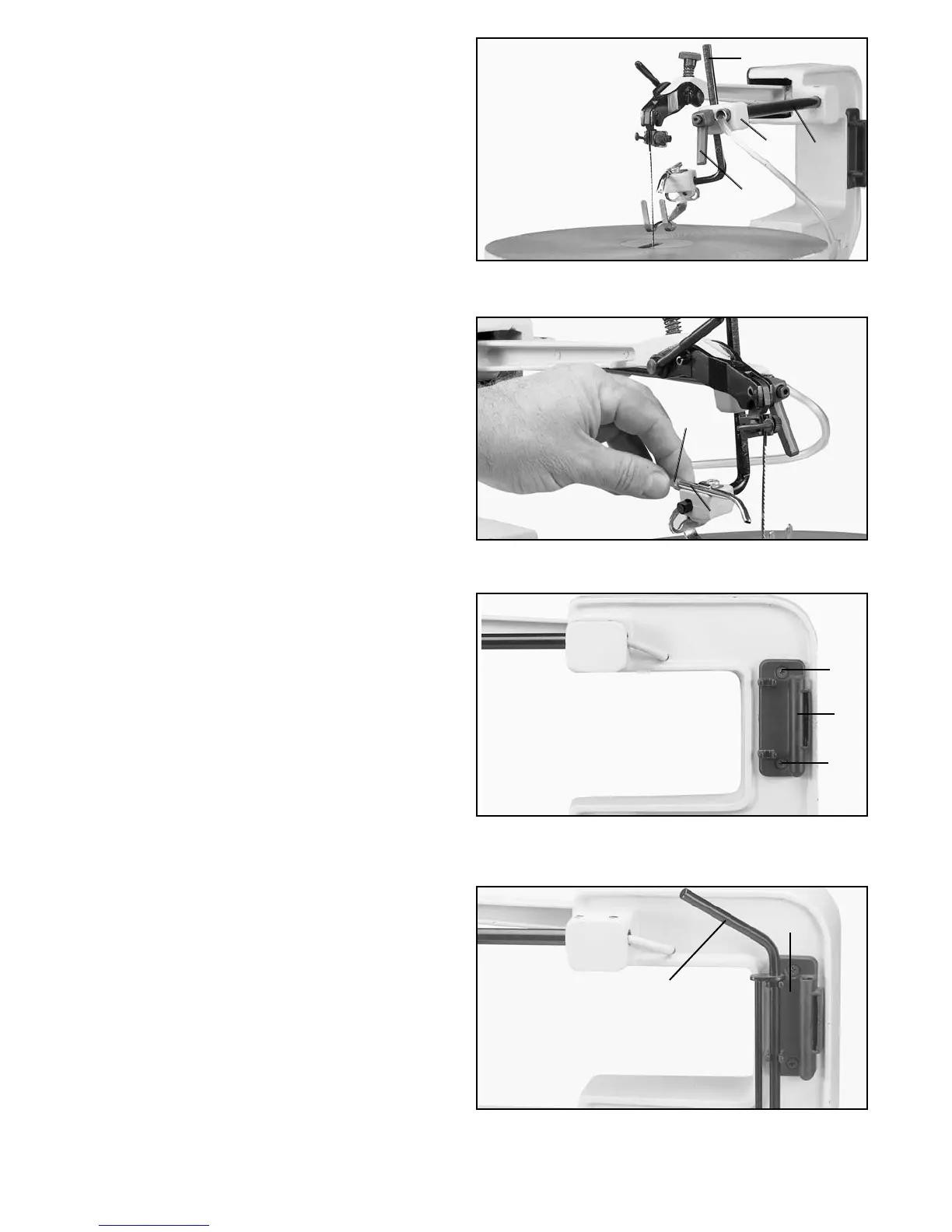
Fig. 11
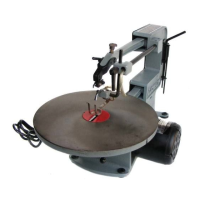
Fig. 12
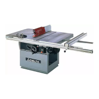
Fig. 13
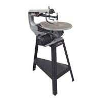
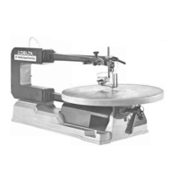
8. Rotate bracket (M) Fig. 10, back to its original posi-
tion as shown, and tighten the two screws that fasten
bracket (M) to rod (N). These screws were loosened in
STEP 6. Then tighten lockhandle (R) to hold rod (S) in
position.
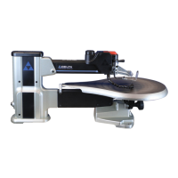
9. Slide end of chip blower tube (T) Fig. 11, onto end of
air nozzle (V), as shown.
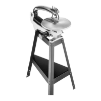
10. Assemble tool holder (X) Fig. 12, to the right side of
the scroll saw using two screws (W).
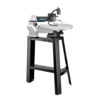
11. The tool holder(X) Fig. 13, is used to hold the quick-
set blade changing wrench (Y), (for removing blade from
lower blade holder), allen wrench and extra blades.
12. Refer to sections "CHANGING BLADES" and
"ADJUSTING BLADE TENSION" for assembling blade
and applying correct tension on the saw blade.
T
V
W
W
X
Y
X
M
N
S
R