Chapter 8 Parameters ASDA-A2
8-18 Revision February, 2017
14:Main circuit voltage (BUS voltage) [Volt]
15:Load/motor inertia ratio [0.1times]
16:IGBT temperature
17:The frequency of resonance suppression
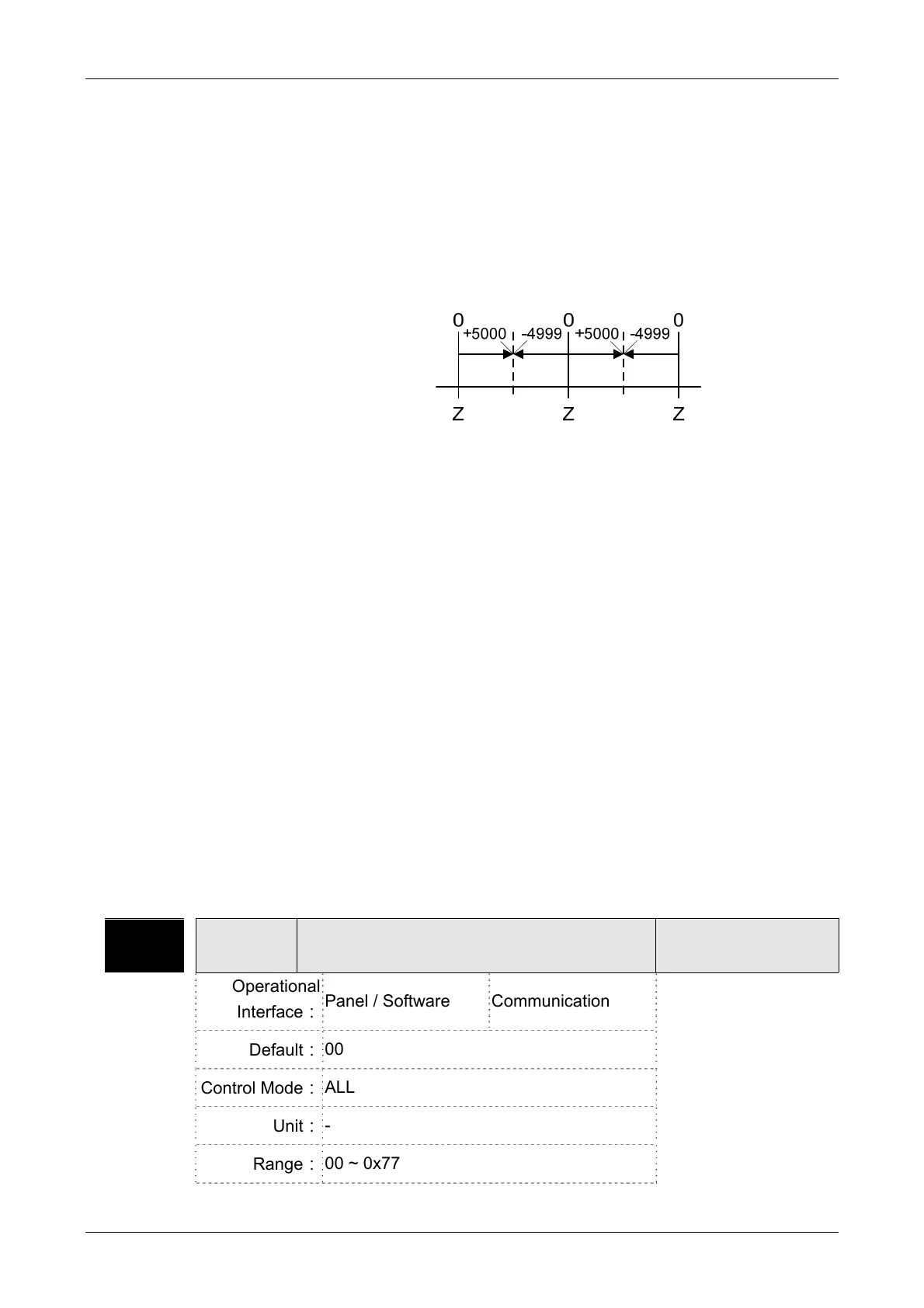
18:The distance from the current position to Z. The range of the
value is between -5000 and +5000;
The interval of the two Z-phase pulse command if 10000 Pulse.
19:Mapping Parameter #1:P0 - 25
20:Mapping Parameter #2:P0 - 26
21:Mapping Parameter #3:P0 - 27
22:Mapping Parameter #4:P0 - 28
23:Monitoring variable #1:P0 - 09
24:Monitoring variable #2:P0 - 10
25:Monitoring variable #3:P0 - 11
26:Monitoring variable #4:P0 - 12
38:It display the battery voltage [0.1 Volt]. For example, if it displays
36, it means the battery voltage is 3.6 V.
72:Analog speed command [0.1 r/min] (This is supported by A2-M/-
U/-L.)
P0-03 MON Analog Output Monitor
Address: 0006H
0007H
Operational
Interface:
Panel / Software Communication
Related Section: 6.6.4
Default:
00
Control Mode:
ALL
Unit:
-
Range:
00 ~ 0x77
 Loading...
