Chapter 3 Wiring ASDA-A2R Series
Revision December, 2014
3-65
Applicable Model
ASD-A2R-0121-
□
, ASD-A2R-0221-
□
, ASD-A2R-0421-
□
, ASD-A2R-1021-
□
,
ASD-A2R-1521-
□
, ASD-A2R-2023-
□
, ASD-A2R-3023-
□
, (
□
=F,L,M,U)
ASD-S-3023-F, ASD-S-4523-F, ASD-S-5523-F, ASD-S-7523-F
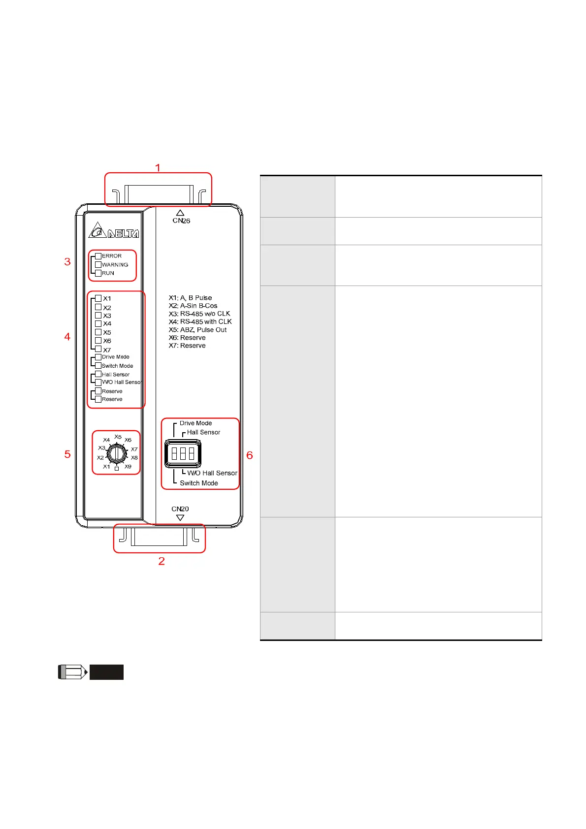
Appearance
1. Signal
source
connector
CN26, 26 pin connector
2. Drive
connector
CN20, 20 pin connector
3. Status
indicators
ERROR: Error LED*
WARNING: Warning LED*
RUN: LED for normal operation
4. Function
indicators
X1: Signal source is square digital
signal
X2: Signal source is sinusoidal analog
signal
X3~X5: Reserved
X6~7: Reserved
Drive Mode: Servo drive issues the
command to control the status of
converter box. The button and the
switch do not work at the moment.
Switch Mode: The status of converter
box is controlled by the button and the
switch. The command issued by servo
drive does not work.
Hall Sensor: Hall sensor is installed.
W/O Hall Sensor: Hall sensor is not
installed.
5. Signal
switch
Use a flat screwdriver to rotate the
switch.
X1: Signal source is square digital
signal
X2: Signal source is sinusoidal analog
signal
X3~X9: Reserved
6. Function
switch
Select the desired function by
switching the switch up and down.
NOTE
1) When an alarm occurs, the ERROR LED will light up and shows the alarm
code on servo drive’s LED display. Users could refer to troubleshooting
section for alarm descriptions and corrective actions.
2) When a warning occurs, the WARNING LED will light up and shows the
warning code on servo drive’s LED display. Users could refer to
troubleshooting section for alarm descriptions and corrective actions.
Specification

 Loading...