EasyManua.ls Logo

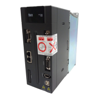
Delta ASD-A2R-1B43 Series

Delta ASD-A2R-1B43 Series
660 pages
To Next Page IconTo Next Page
Loading...
A High Performance with
Diverse Communication
Interfaces Servo Drive
ASDA-A2R
Series User
Manual
www.deltaww.com
A High Performance with Diverse Communication
Interfaces Servo Drive
ASDA-A2R
Series User Manual
Industrial Automation Headquarters
Delta Electronics, Inc.
Taoyuan Technology Center
No.18, Xinglong Rd., Taoyuan City,
Taoyuan County 33068, Taiwan
TEL: 886-3-362-6301 / FAX: 886-3-371-6301
Asia
Delta Electronics (Jiangsu) Ltd.
Wujiang Plant 3
1688 Jiangxing East Road,
Wujiang Economic Development Zone
Wujiang City, Jiang Su Province, P.R.C. 215200
TEL: 86-512-6340-3008 / FAX: 86-769-6340-7290
Delta Greentech (China) Co., Ltd.
238 Min-Xia Road, Pudong District,
ShangHai, P.R.C. 201209
TEL: 86-21-58635678 / FAX: 86-21-58630003
Delta Electronics (Japan), Inc.
Tokyo Ofce
2-1-14 Minato-ku Shibadaimon,
Tokyo 105-0012, Japan
TEL: 81-3-5733-1111 / FAX: 81-3-5733-1211
Delta Electronics (Korea), Inc.
1511, Byucksan Digital Valley 6-cha, Gasan-dong,
Geumcheon-gu, Seoul, Korea, 153-704
TEL: 82-2-515-5303 / FAX: 82-2-515-5302
Delta Electronics Int’l (S) Pte Ltd.
4 Kaki Bukit Ave 1, #05-05, Singapore 417939
TEL: 65-6747-5155 / FAX: 65-6744-9228
Delta Electronics (India) Pvt. Ltd.
Plot No 43 Sector 35, HSIIDC
Gurgaon, PIN 122001, Haryana, India
TEL : 91-124-4874900 / FAX : 91-124-4874945
Americas
Delta Products Corporation (USA)
Raleigh Ofce
P.O. Box 12173,5101 Davis Drive,
Research Triangle Park, NC 27709, U.S.A.
TEL: 1-919-767-3800 / FAX: 1-919-767-8080
Delta Greentech (Brasil) S.A.
Sao Paulo Ofce
Rua Itapeva, 26 - 3° andar Edicio Itapeva One-Bela Vista
01332-000-São Paulo-SP-Brazil
TEL: 55 11 3568-3855 / FAX: 55 11 3568-3865
Europe
Deltronics (The Netherlands) B.V.
Eindhoven Ofce
De Witbogt 15, 5652 AG Eindhoven, The Netherlands
TEL: 31-40-2592850 / FAX: 31-40-2592851
*We reserve the right to change the information in this manual without prior notice.
DELTA_IA-ASDA-A2R_UM_EN_20141219 (V2.0)

Table of Contents

Question and Answer IconNeed help?

Do you have a question about the Delta ASD-A2R-1B43 Series and is the answer not in the manual?

Delta ASD-A2R-1B43 Series Specifications

General IconGeneral
BrandDelta
ModelASD-A2R-1B43 Series
CategoryServo Drives
LanguageEnglish

Summary

Preface

Safety Precautions

Details critical safety measures and warnings to be observed before and during operation, installation, and wiring.

Chapter 1 Inspection and Model Explanation

Chapter 2 Installation

2.3 Ambient Conditions of Installation

Specifies the environmental requirements for installing the servo drive and motor, including temperature, humidity, and contamination levels.

Chapter 3 Wiring

3.1 Wiring of Deltas Servo System

Details the wiring methods for Delta's servo systems, including diagrams and notes for peripheral device connections.

3.1.1 Wiring Diagram of Peripheral Devices (connect to Deltas Servo Motor (Communication Type))

Provides a wiring diagram for connecting peripheral devices to the servo motor using communication interfaces.

3.1.2 Connectors and Terminals of the Servo Drive

Lists and describes all terminal signals and connectors on the servo drive for various functions like power input and communication.

3.1.3 Wiring Method

Illustrates the wiring methods for single-phase and three-phase power supplies, explaining the function of contacts and coils.

3.2 Schematic Diagram of Servo System

Presents schematic diagrams of the servo system, illustrating connections for different models and regenerative resistor configurations.

3.3 IO Signal (CN1) Connection

Details the I/O signals for CN1, including digital inputs, outputs, encoder signals, and analog command inputs.

3.4 CN2 Connector

Describes the terminal blocks and pin numbers for the CN2 connector, covering both encoder and motor connections.

3.5 Wiring of CN3 Connector

Explains the wiring of the CN3 connector for PC communication via RS-232 and RS-485, including pin definitions.

3.7 CN5 Connector (Full-closed Loop)

Explains the CN5 connector for full-closed loop control, connecting to linear scales or encoders for precise position feedback.

3.8 CN6 Connector (CANopen)

Describes the CN6 connector for CANopen communication, supporting position, torque, and speed modes.

3.10 Standard Wiring Method

Provides standard wiring diagrams for various control modes like Position (PT), Position (PR), Speed, and Torque.

Chapter 4 Panel Display and Operation

4.2 Parameter Setting Procedure

Details the step-by-step procedure for switching between modes and operating within Monitor, Parameter, and Alarm modes.

Chapter 5 Trial Operation and Tuning

5.1 Inspection without Load

Covers the initial inspection steps before powering the servo drive, ensuring no damage or loose parts.

5.2 Apply Power to the Servo Drive

Provides instructions on how to correctly apply power to the servo drive, including wiring checks and power-on display information.

5.3 JOG Trial Run without Load

Details the procedure for performing a JOG trial run without load, recommended for safety and initial testing.

5.6 Tuning Procedure

Provides comprehensive procedures for tuning the servo motor, including inertia estimation and auto/semi-auto tuning.

Chapter 6 Control Mode of Operation

6.1 Selection of Operation Mode

Lists and describes the available single, dual, and multi-mode operations for position, speed, and torque control.

Chapter 7 Motion Control

Chapter 8 Parameters

8.2 List of Parameters

Provides a comprehensive list of all parameters, including their abbreviation, function, default value, and related sections.

8.3 Parameter Description

Offers detailed descriptions for each parameter group, explaining their function, interface, default settings, and related sections.

Chapter 9 Communication

Chapter 10 Troubleshooting

10.1 Alarm of Servo Drive

Lists servo drive alarms, their descriptions, corresponding DO signals, and the servo status for each alarm.

10.4 Causes and Corrective Actions

Explains the common causes and corrective actions for various servo drive alarms like over current, over voltage, and motor errors.

10.5 Corrective Actions after the Alarm Occurs

Provides specific corrective actions for various alarms, including reset procedures and re-powering instructions.

Chapter 11 Specifications

Chapter 12 Setting of Motor Parameters

12.1 Tuning Procedure of Motor Parameters

Guides users through the process of tuning motor parameters using PC software or the panel, emphasizing safety precautions.

Related product manuals