EasyManua.ls Logo

Delta ASD-A2R-0221 Series User Manual

Delta ASD-A2R-0221 Series
660 pages
To Next Page IconTo Next Page
To Previous Page IconTo Previous Page
Page #229 background imageLoading...
Page #229 background image
Chapter 7 Motion Control ASDA-A2R Series
Revision December, 2014 7-35
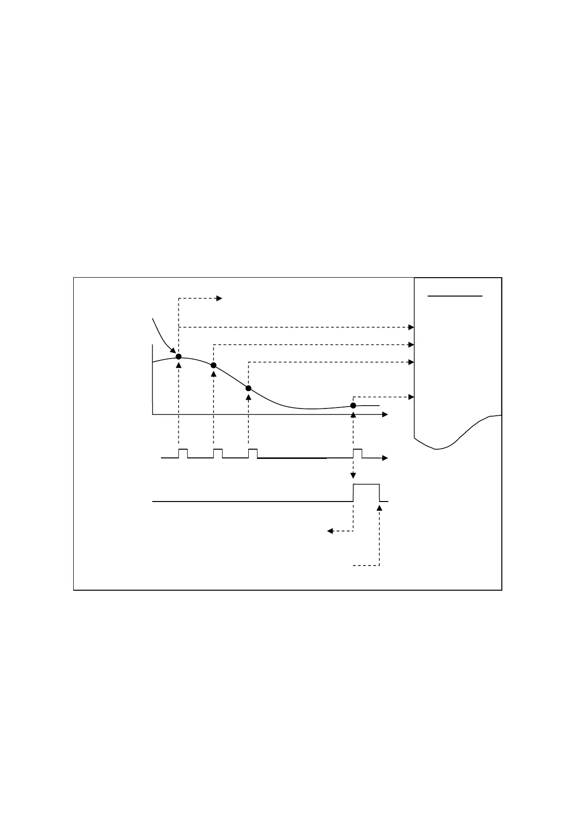
The CAP data is saved in data array and the first CAP data locates in P5-36. The CAP
number has no limit, thus it can be set via P5-38. The last CAP data is saved in P5-36
P5-381. Set the value of P5-39 X, Bit0 to 1 so as to activate CAP function. Every
time when DI7 is triggered, one data will be captured and saved in data array. Then, the
value of P5-38 will decrease one automatically until the CAP number reaches the
setting value (P5-38 = 0). The CAP procedure is completed, the setting value of P5-39
X, Bit0 will be cleared to 0 and DO.CAP_OK is ON.
When capturing the first data, the position of CAP axis can be reset. The first CAP value
will be the value set by P5-76. And the value of the second CAP data will be the
incremental value from the first data. This method is called Relative Capture. If not
selecting the first data reset, it is called Absolute Capture.
When capturing the first data, it automatically activates COMPARE function, which
means the COMPARE function is activated via DI5.
The diagram of CAP:
Position of
CAP Axis
(P5-37)
CAP signal:
(DI7)
DO.CAP_OK:
1 2 3 N
Data Array
…..
POS 1
POS 2
POS 3
~
POS N
CAP is completed and set P5-39.X0 to 0.
PR procedure #50 can be triggered.
The CAP number is
set via P5-38
P5-39.X0=1 to activate the next CAP and switch off DO.
The 1
st
axis
position can
be reset to
the value as
P5-76
The 1
st
p
oint is saved in P5-36.
The 2nd
p
oint is saved in P5-36+1.
The 3
rd
p
oint is saved in P5-36+2
Automatically activate COMPARE

Table of Contents

Question and Answer IconNeed help?

Do you have a question about the Delta ASD-A2R-0221 Series and is the answer not in the manual?

Delta ASD-A2R-0221 Series Specifications

General IconGeneral
ModelASD-A2R-0221
TypeServo Drive
Rated Output Power2.2 kW
Power Supply Voltage200-230V AC
Max. Input Frequency500 kHz
Control ModePosition, Speed, Torque
Communication InterfaceRS-485, CANopen
Cooling MethodNatural Cooling
SeriesASD-A2R
Power SupplyThree-phase
Control MethodPWM Control
Protection FeaturesOverload, Overvoltage, Undervoltage, Overcurrent
Operating Temperature0°C to 50°C
Storage Temperature-20°C to 65°C
Humidity20% to 90% RH (non-condensing)
Vibration5.9 m/s²

Summary

Preface

Safety Precautions

General safety guidelines, inspection, installation, wiring, operation, and maintenance precautions.

Main Circuit Wiring

Guidelines for wiring the main circuit, including power supply and motor output connections.

Safety Precautions for Linear Motors

Specific safety measures when connecting to linear motors, including electrical hazards and temperature warnings.

Chapter 2 Installation

2.7 Selection of Regenerative Resistor

Guidance on selecting regenerative resistors for built-in and external use based on servo drive specifications.

Chapter 3 Wiring

3.1 Wiring of Delta’s Servo System

Details on wiring Delta’s servo system, including peripheral devices and motor connections.

I/O Signal (CN1) Connection

Details on connecting I/O signals to CN1, including terminal layouts and signal explanations.

Standard Wiring Method

Standard wiring diagrams for common control modes like PT, PR, Speed, and Torque.

Chapter 4 Panel Display and Operation

4.2 Parameter Setting Procedure

Step-by-step guide for setting parameters using the panel interface.

4.4 General Function

Details on general functions like fault record display, JOG mode, and force DO output.

Chapter 5 Trial Operation and Tuning

5.1 Inspection without Load

Procedure for inspecting the servo motor and drive without applying load, focusing on safety.

5.2 Apply Power to the Servo Drive

Instructions for safely applying power to the servo drive and initial checks.

5.6 Tuning Procedure

Procedures for tuning motor parameters, including inertia estimation and auto/semi-auto tuning methods.

Chapter 6 Control Mode of Operation

6.2 Position Mode

Details on position command input methods (PT, PR) and control structures.

6.3 Speed Mode

Details on speed command input methods (analog, register) and control structures.

6.4 Torque (force) Mode

Details on torque command input methods (analog, register) and control structures.

Chapter 7 Motion Control

7.8 Homing Description of PR Mode

Procedure and description of the homing function in PR mode, including Z pulse and coordinate setting.

7.10 Parameter Settings in PR Mode

Detailed description of parameters for target speed, acceleration/deceleration, and path definitions in PR mode.

Chapter 8 Parameters

8.3 Parameter Description

Detailed description of various parameters including Monitor, Filter, Gain, Position, Speed, Torque, and Communication parameters.

Chapter 9 Communication

9.1 RS-485 / RS-232 Communication Hardware Interface

Description of RS-232 and RS-485 communication interfaces, including wiring and configuration.

Chapter 10 Troubleshooting

10.1 Alarm of Servo Drive

List of servo drive alarms, their descriptions, corresponding DO signals, and servo status.

10.2 Alarm of CANopen Communication

List of alarms related to CANopen communication, including error descriptions and corrective actions.

10.3 Alarm of Motion Control

List of alarms related to motion control, including causes and corrective actions.

10.4 Causes and Corrective Actions

Detailed breakdown of common causes and corrective actions for various servo drive alarms.

10.5 Corrective Actions after the Alarm Occurs

General corrective actions for specific alarms like Over current, Over voltage, Under voltage, and Encoder errors.

Chapter 12 Setting of Motor Parameters

12.1 Tuning Procedure of Motor Parameters

Step-by-step guide for tuning motor parameters using PC software or the panel interface.

Related product manuals