Chapter 3 Wiring ASDA-A2R Series
3-24 Revision December. 2014
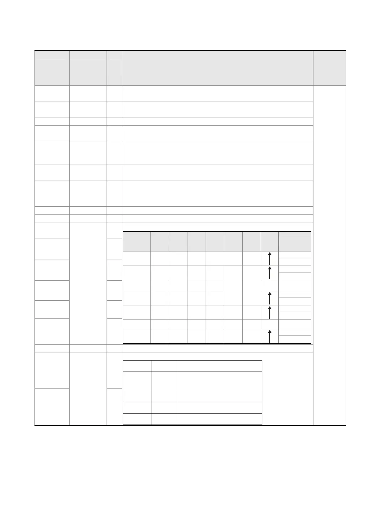
The explanation of DI signal default setting is as the followings
DI Signal
Name
Operation
Mode
Pin
No
Function
Wiring
Method
(Refer to
3.4.3)
SON ALL 9
When DI is ON, the servo circuit will be activated and the
motor coil will generate current.
C9/C10
C11/C12
ARST ALL 33
When the alarm (ALRM) occurs, this signal is used to reset the
servo drive and output the signal, Ready (SRDY) again.
GAINUP ALL - It is for switching the controller gain.
CCLR PT, PR 10
It is for clearing the deviation counter.
ZCLAMP ALL -
When this DI is ON and the motor speed is slower than the
setting of P1-38, the motor position will be locked when the
signal is triggered.
CMDINV PR, T, S -
When this DI is ON, the motor will operate in the opposite
direction.
CTRG
PR,
PR-S,
PR-T
10
In PR mode, the moment CTRG is ON (rising edge), save the
position command selected by POS0~2 into the controller and
then trigger the command.
TRQLM S,Sz 10 ON means the torque limit command is effective.
SPDLM T, Tz 10 ON means the speed limit command is effective.
POS0
P, PR-S,
PR-T
34
In PR mode, the source of position command:
Position
Comman
d
POS5 POS4 POS3 POS2 POS1 POS0 CTRG
Corresponding
parameter
P1 0 0 0 0 0 0
P6-00
P6-01
P2 0 0 0 0 0 1
P6-02
P6-03
~ ~
P50 1 1 0 0 1 0
P6-98
P6-99
P51 1 1 0 0 1 1
P7-00
P7-01
~ ~
P64 1 1 1 1 1 1
P7-26
P7-27
POS1 8
POS2 -
POS3 -
POS4 -
POS5 -
STOP - - Stop
SPD0
S, Sz,
PT-S,
PR-S, S-T
34
The source of selecting speed command:
SPD1 SPD0 Command Source
0 0 S mode is analog input
while Sz mode is 0.
0 1 P1-09
1 0 P1-10
1 1 P1-11
SPD1 8

 Loading...