- 5 -
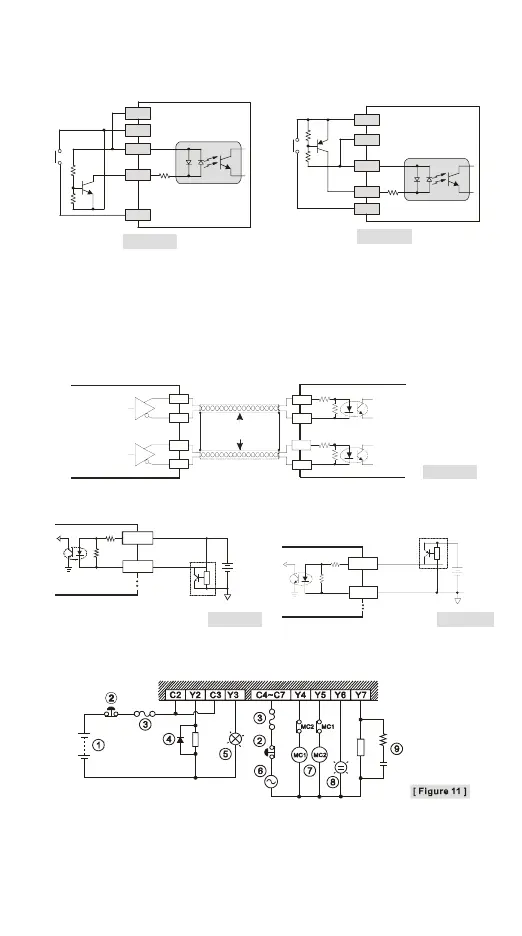
There are 2 types of DC inputs, SINK and SOURCE. (See the example below. For
detailed point configuration, please refer to the specification of each model.)
y DC Signal IN – SINK mode
Input point loop equivalent circuit
y DC Signal IN – SOURCE mode
Input point loop equivalent circuit
24G
+24V
S/S
X0
X1
[ Figure 6 ]
+24V
24G
S/S
X0
X1
[ Figure 7 ]
Wiring of Differential Inputs
A0 to A1 and B0 to B1 of DVP-20PM series are all 5 to 24 VDC high-speed input circuit
and others are 24 VDC inputs. The working frequency of high-speed input circuits can
reach up to 200 kHz and is mainly for connecting to differential (double-wire) LINE
DRIVER output circuits.
y Wiring in a high-speed, high-noise environment
A +
A -
B +
B -
A
B
A0+
A0-
B0+
B0-
DVP-20PM high-speed inpu
Encoder output
Differential output
Twisted pair
cable
[ Figure 8 ]
In a low-noise and low-frequency (less than 50 kHz) environment, you may also use 5 to
24 VDC SINK/SOURCE input of a single port.
SINK
NPN
Sensor
+
5~24V
PG0+
PG0 -
[ Figure 9 ]
SOURCE
+
5~24V
PNP
Sensor
PG0+
PG0 -
[ Figure 10 ]
Output Point Wirings
y Relay (R) contact circuit wiring

 Loading...


