- 6 -
c DC power supply d Emergency stop: Uses external switch
e Fuse: Uses 5 to10 A fuse at the shared terminal of output contacts to protect the output
circuit
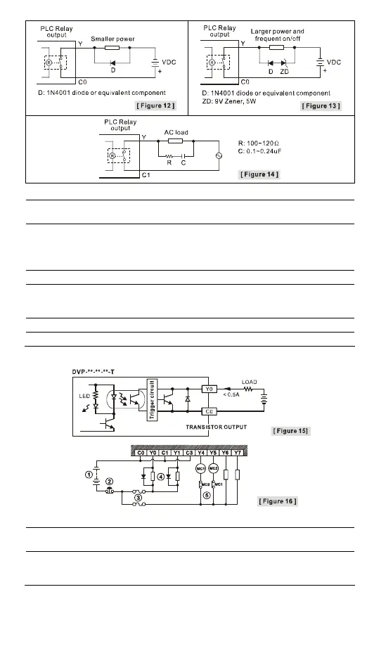
f Transient voltage suppressor: To extend the life span of contact
1. Diode suppression of DC load: Used when in smaller power (Figure 12)
2. Diode + Zener suppression of DC load: Used when in larger power and frequent On/Off
(Figure 13)
g Incandescent light (resistive load) h AC power supply
i Manually exclusive output: For example, Y4 and Y5 control the forward running and reverse
running of the motor, forming an interlock for the external circuit, together with the PLC
internal program, to ensure safe protection in case of any unexpected errors.
j Neon indicator
k Absorber: To reduce the interference on AC load (Figure 14)
y Transistor (T) contact circuit wiring
c DC power supply d Emergency stop e Circuit protection fuse
f The output of the transistor model is “open collector”. If Y0/Y1 is set to pulse output, the
output current has to be bigger than 0.1 A to ensure normal operation of the model.
g Manually exclusive output: For example, Y4 and Y5 control the forward running and reverse
running of the motor, forming an interlock for the external circuit, together with the PLC
internal program, to ensure safe protection in case of any unexpected errors.
Wiring of Differential Outputs

 Loading...


