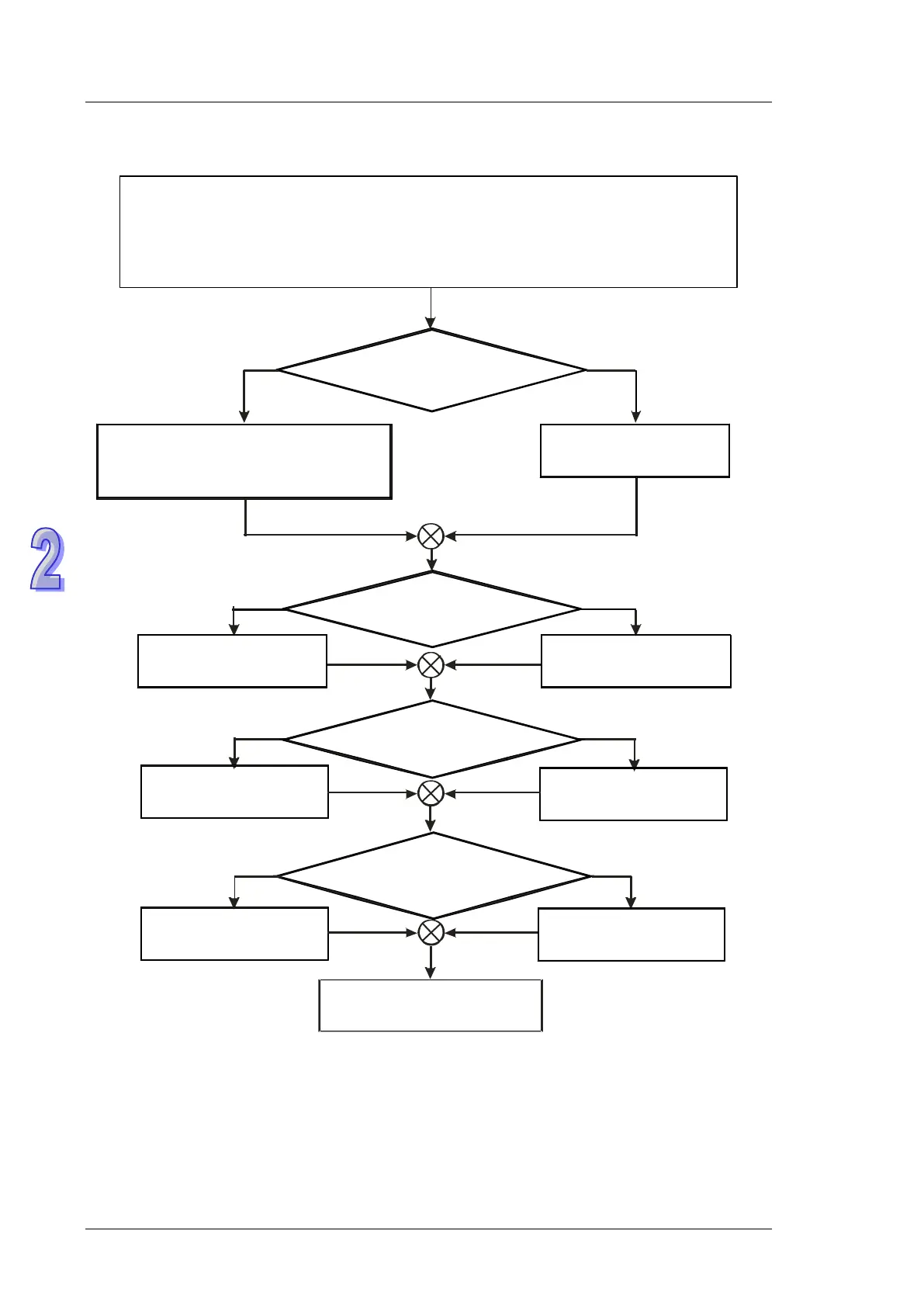
13. Operation flow chart: In the flow chart below, there are 16 connections, and 50 words are
accessed.
Disable this
function
Enable this
function
Set M1355 to ON
Set the data length to
read/write for
connections
Enable access up to
50
words through PLC LINK
Enable auto or
manual mode on
PLC LINK
Enable manual mode
Enable auto mode
SET M1350 to ON
Enable PLC LINK
Activate the establishment of
connection manually.
Communication
with Modbus H17
funciton
D1355-D1370: Setting the starting address for PLC LINK connection #1-16 to read.
D1434-D1449: Setting the data length to be read for PLC LINK connection ID
#1-16.
D1415-D1430: Setting the starting address for PLC LINK connection #1-16 to write.
D1450-D1465: Setting the data length to be written for PLC LINK connection ID#1-16.
(If there is no current setting value, PLC uses the previous setting value instead.)
M1360~M1375: Activation status of
connection ID#1-16
Set M1355 to OFF
Enable this
function
Disable this
function
Set M1354 to OFFSet M1354 to ON
Set M1353 to ON
Set M1353 to ON
Set M1351 to ON
Set M1352
to ON;
Setting times for PLC LINK
polling cycle (D1431)
Enable access up to 16
words through PLC LINK