DVP-ES2/EX2/EC5/SS2/SA2/SX2/SE&TP Operation Manual - Programming
D100 ~ D115 of Connection ID#2
D200 ~ D215 of Connection ID#2
d) Up to16 Slaves can be accessed through PLC LINK. For allocation of D100 ~ D115 and
D200 ~ D215 in each Slave PLC, please refer to the tables of Special M and Special D of
this function in previous pages.
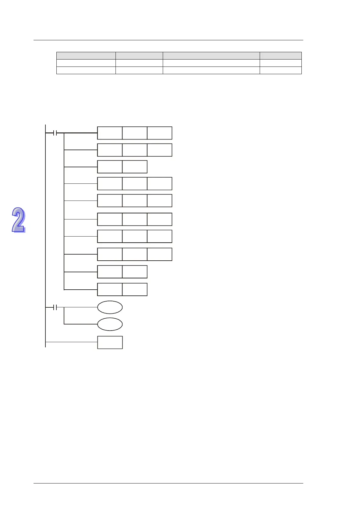
15. Example 2: Conncet DVP-PLC with VFD-M inverter and control the RUN, STOP, Forward
operation, Reverse operation through PLC LINK.
a) Write the ladder diagram program into Master PLC (ID#17)
M1002
MOV K17 D1121
H86 D1120
K6
K2
M1351
END
MOV
SET M1120
MOV
MOV
D1434
D1450
M1350
X1
H2100
H2000
MOV
MOV
D1355
D1415
Starting reference of data
to be written on Slave
Starting reference of data
to be read on Slave
Data length to be read
Data length to be witten
Retain communication setting
COM2 communication protocol
Master ID#
Auto mode
Enable EASY PLC LINK
SET M1355
Set the Slave to be linked manually
SET M1360
K1MOV
D1399
ID# of the starting Slave
Link Slave ID#1
b) M1355 = ON. Set the Slave to be linked manually by M1360~M1375. Set ON M1360 to
link Connection ID#1.
c) Address H2100-H2105 maps to registers D1480-D1485 of PLC. When X1 = ON, PLC
LINK executes, and the data in H2100-H2105 will be displayed in D1480-D1485.
d) Address H2000-H2001 maps to registers D1496-D1497 of PLC. When X1 = ON, PLC LINK
executes, and the parameter in H2000-H2001 will be specified by D1496-D1497.
e) Commands of VFD can be specified by changing the value in D1496. (e.g. D1496 =
H12=>VFD forward operation; D1496 = H1=> VFD stops)
f) Frequency of VFD can be specified by changing the value in D1497. (e.g. D1497 = K5000,
set VFD frequency as 50kHz.)
g) In addition to VFD AC motor drives, devices support MODBUS protocol such as DTA/DTB
temperature controllers and ASDA servo drives can also be connected as Slaves. Up to 16
Slaves can be connected.
16. TD1354 is a PLC link scan cycle (unit: 1ms), and max. display value is K32000. D1354 = K0
when PLC Link stops or when the first scan is completed.