3. Instruction Set
Program Example 3:
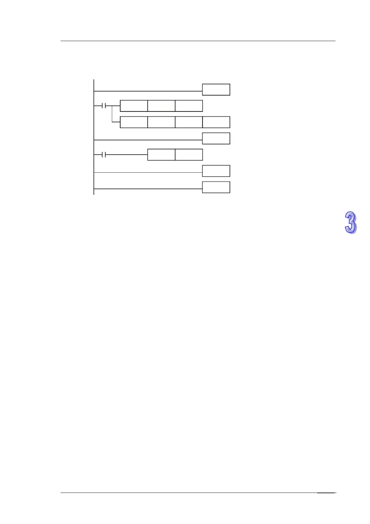
Executes interrupt subroutine by applying software comparator.
M1000
DCNT
C235 K100
DHSCS
C235
K100
I010
EI
FEND
I010
M1000
OUT
Y10
IRET
END
When value in C235 varies from 99 to100, interrupt subroutine triggered by I010 executes
immediately to set Y0 ON.
Points to note:
If operand D is specified as S, M or Y0~Y3 for the above high speed comparison, the
compare result will immediately output to the external points Y0~Y3 (Y0~Y5 for SS2/SX2).
However, if D is specified as Y4~Y337, external outputs will be updated till the end of
program (delay for one scan cycle).
1. Count value storage function of high speed interrupt:
When X1, X3, X4 and X5 is applied for reset function and associated external interrupts are
disabled, users can define the reset function as Rising/Falling-edge triggered by special M
relays specified in the table: Applicable Software High Speed Counters. However, if
external interrupts are applied, the interrupt instructions have the priority in using the input
points. In addition, PLC will move the current data in the counters to the associated data
registers below then reset the counters
When X0 (counter input) and X1 (external Interrupt I100/I101) work with C243, the count
value will be moved to D1240 and D1241 when interrupt occurs and then the counter will be
reset.
When X2 (counter input) and X3 (external Interrupt I300/I301) work with C244, the count
value will be moved to D1242 and D1243 when interrupt occurs and then the counter will be
reset.
When X0 (counter input) and X4 (external Interrupt I400/I401) work with C246, C248, C252,
the count value will be moved to D1240 and D1241 when interrupt occurs and then the
counter will be reset.